Overload Breaker protector principle
What is an overload protector?
Overload Breaker protectors are often referred to as:
Torque Holder, Overload Breaker Protector, Torque Clutch, Torque Clutch, Limiter, Axial Load Overload Breaker Protector, Torsion Limiter, Safety Clutch, Safety Coupling, Force Limiting Clutch, Clutch Limiter, Ball Clutch, Friction Clutch.
The role of the overload protector:
It is often installed between the main and passive sides of the power transmission. When an overload fault occurs (torque exceeds the set value), the torque limiter will separate, thus effectively protecting the drive machinery and the load;
The common form is:
Friction torque limiter and ball torque limiter.
The installation structure of the torque limiter is:
Shaft-axis, shaft-flange, shaft-synchronous pulley, shaft-sprocket, shaft-gear, shaft-belt, etc.
The overload protector is a circuit protection device designed according to the actual needs of the electrical control industry. It adopts single-chip technology, complete functions, reliable action, strong anti-interference ability, and adapt to the harsh working environment. It can provide effective protection for over-current, short-circuit, phase loss, phase imbalance, phase misalignment and startup process (avoiding overcurrent) of electrical systems, squirrel cage motors, and wound motor.
The overload protector samples the signal from the current transformer, converts each phase load current into a voltage signal proportional to it, and inputs the signal and all control signals to the microprocessor. The microprocessor continuously collects, calculates, and stores various signals, compares them with corresponding conditions, and then outputs the results.
Leakage protector overload protection circuit schematic
As shown in the figure, the R3, RP voltage divider circuit draws the overvoltage signal of the mains, and drives the micro-trigger thyristor through the trigger diode to make the tripper act. The overload protection of the leakage protector is completed by the remnant winding coil Lg using the residual current principle.
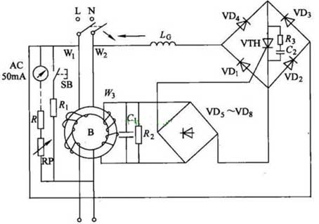
The normally open contact of the reed switch is connected to the test button SB; The coil Lg is connected in series to the winding W1. When the load current exceeds the set value (the overload setting value is determined by the wire diameter and the number of turns of the coil), the normally open contact of the reed switch is closed due to magnetization. When the test button SB is closed, the residual current is generated on the primary side of the transformer T, and the secondary side signal triggers the VTH to be turned on, and the trip unit operates to quickly cut off the power. The electrical principle is the same as that of the leakage and overvoltage protection described above. The circuit shown in the figure below completely protects against overvoltage, overcurrent, overload, and leakage.
Overload Breaker protectors are often referred to as:
Torque Holder, Overload Breaker Protector, Torque Clutch, Torque Clutch, Limiter, Axial Load Overload Breaker Protector, Torsion Limiter, Safety Clutch, Safety Coupling, Force Limiting Clutch, Clutch Limiter, Ball Clutch, Friction Clutch.
The role of the overload protector:
It is often installed between the main and passive sides of the power transmission. When an overload fault occurs (torque exceeds the set value), the torque limiter will separate, thus effectively protecting the drive machinery and the load;
The common form is:
Friction torque limiter and ball torque limiter.
The installation structure of the torque limiter is:
Shaft-axis, shaft-flange, shaft-synchronous pulley, shaft-sprocket, shaft-gear, shaft-belt, etc.
The overload protector is a circuit protection device designed according to the actual needs of the electrical control industry. It adopts single-chip technology, complete functions, reliable action, strong anti-interference ability, and adapt to the harsh working environment. It can provide effective protection for over-current, short-circuit, phase loss, phase imbalance, phase misalignment and startup process (avoiding overcurrent) of electrical systems, squirrel cage motors, and wound motor.
The overload protector samples the signal from the current transformer, converts each phase load current into a voltage signal proportional to it, and inputs the signal and all control signals to the microprocessor. The microprocessor continuously collects, calculates, and stores various signals, compares them with corresponding conditions, and then outputs the results.
Leakage protector overload protection circuit schematic
As shown in the figure, the R3, RP voltage divider circuit draws the overvoltage signal of the mains, and drives the micro-trigger thyristor through the trigger diode to make the tripper act. The overload protection of the leakage protector is completed by the remnant winding coil Lg using the residual current principle.
The normally open contact of the reed switch is connected to the test button SB; The coil Lg is connected in series to the winding W1. When the load current exceeds the set value (the overload setting value is determined by the wire diameter and the number of turns of the coil), the normally open contact of the reed switch is closed due to magnetization. When the test button SB is closed, the residual current is generated on the primary side of the transformer T, and the secondary side signal triggers the VTH to be turned on, and the trip unit operates to quickly cut off the power. The electrical principle is the same as that of the leakage and overvoltage protection described above. The circuit shown in the figure below completely protects against overvoltage, overcurrent, overload, and leakage.


