Function of motor overload protector
Do you know what a motor overload protector is? Do you know the design of the motor overload protection circuit? Motor overload means that a general motor has a fixed operating power, called rated power, in watts (W). If the actual power of the motor exceeds the rated power of the motor under certain circumstances, this phenomenon is called motor overload.
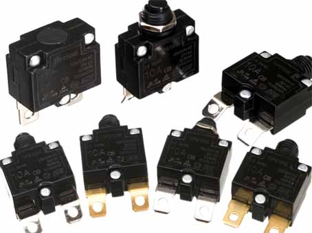
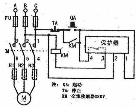
There is a thermal overload protector in the main circuit of the motor. When the motor is overloaded, the overload protector acts, the normally closed contact cuts off the control circuit, and the normally open contact closes and turns on the indicator light. After the overload is eliminated, the contacts of the overload protector can be reset in two ways to make the circuit work again: Manual reset-need to press the reset button; Automatic reset-the overload is removed, wait a while, it will automatically return to normal after cooling down.
If it is a manual reset, after finding the overload protector, press the red handle on it, and you can hear a "pop" sound. You can turn on the power.
Simple motor overload protection circuit
Function introduction of the circuit:
The circuit can realize that when the motor is overloaded, the comparator outputs a high level signal to light up the overload indicator. But the protection link of the circuit is omitted and can be realized with a relay.
The whole circuit working process:
The whole circuit is relatively simple, somewhat similar to the undervoltage protection circuit of a motor.
First of all, we need to know that the problem of motor overload and normal operation is: current.
When the motor is overloaded, the current flowing in the circuit is higher than the current during normal operation. According to this phenomenon, we use the comparator to set a threshold so that when the motor is normal, the comparator does not send out an overload signal;
When the motor is overloaded and exceeds this threshold, the comparator outputs an overload signal.
In the circuit, resistors R1 and R6 form a voltage divider reference circuit, which is the threshold voltage we set, connected to the inverting input of the comparator.
The non-inverting input of the comparator is a simple current-converting voltage circuit, which detects the current flowing through the motor through the voltage on R5.
Among them, R4, C2 and R3, C1 are two simple RC filter circuits.
When the motor is working normally, the voltage at point B should be less than the voltage at point A, the comparator outputs a low level, and the overload indicator D1 is in the off state.
When the motor is overloaded, the current flowing through R5 will increase, the voltage drop on R5 will increase, and the voltage at point B will increase. When the voltage is greater than point A, the comparator outputs a high level, and the overload indicator light is lit. Among them, the LM393 comparator is an OC gate output, so an external pull-up resistor needs to be added, among which R2 is. It is also the current limiting resistor of D1. The above is the analysis of the design principle of the motor overload circuit. I hope to give you some help and help you in the design process.


