Three-phase asynchronous motor temperature control principle
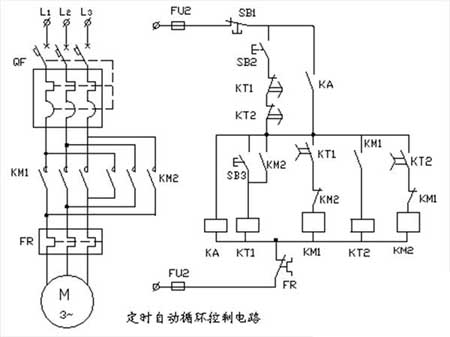
1, timing automatic cycle control circuit
Description:
1. The capacity of the three-phase asynchronous motor in the map is 1.5KW, which requires the circuit to automatically cycle forward and reverse control. The forward rotation maintenance time is 20 seconds, and the reverse rotation maintenance time is 40 seconds.
2. Wiring on the power distribution board according to the schematic diagram requires bright lines, reasonable process and reliable contacts.
3. Briefly describe the working principle of the circuit.
Note: The delay time of the time relay should not be less than 15 seconds, and the time adjustment should be from long to short. Timing automatic cycle control circuit circuit working principle:
Close the power switch QF, press the hold button SB2, and the intermediate relay KA pulls in. The self-protection contact of KA is connected in parallel with the series circuit composed of the break contacts of the buttons SB2, KT1, and KT2, and the start control circuit is connected. When the start button SB3 is pressed, the time relay KT1 is energized. The moving contact KT1 whose power-off delay is open is closed, the coil of the contactor KM1 is energized, the main contact is closed, and the motor is rotating forward (the forward rotation maintaining time is 20 seconds).
At the same time, the KM1 moving contact is connected to the time relay KT2, and the moving contact KT2 which is disconnected in series in the coil circuit of the contactor KM2 is closed. Since the interlocking contact of KM1 is now disconnected, the contactor KM2 coil cannot be energized. When the forward rotation maintenance time is over, the moving contact KT1 with the power-off delay is turned off, KM1 is released, and the motor rotates forward. The break contact of KM1 is closed, the coil of contactor KM2 is energized, the main contact is closed, and the motor starts to reverse. At the same time, the KM1 moving contact opens the time relay KT2 coil circuit (the reverse rotation time starts at 40 seconds). At this time, the KM2 moving contact is connected to the KT1 coil again, and the moving contact KT1 with the power-off delay is closed to prepare for the next forward rotation of the motor.
Therefore, the KM2 interlocking contact in series in the coil circuit of the contactor KM1 is disconnected, and the coil of the contactor KM1 is temporarily not energized. The KT1 and KT2 in series with the button SB2 are closed with a power-off delay to ensure that the control circuit can be restarted after the automatic cycle of the motor is completed. Thermal relay FR normally closed contact, the control circuit is automatically disconnected when the motor is overloaded or the phase is overheated, and the motor is protected.
Description:
1. The starting sequence of this circuit is the first M1 motor and the rear M2 motor; the stopping sequence is reversed.
2. PLC (Mitsubishi FX0N, FX1N), programmer connection and power-on operation.
3, Clear operation
Program write operation; write out the instruction list according to the ladder diagram.
4. Connect the motor to the main sequence control on the main unit.
The working principle of the motor sequence control circuit: close the power switch QS, press the start button SB1, the contactor KM1 is electrically attracted and self-protected, and the M1 motor starts running. The other moving contact of the KM1 is closed to prepare the contactor KM2 for power. When the start button SB2 is pressed, the contactor KM2 is energized and self-protected, and the M2 motor is started. The starting sequence is the first KM1 pull-in, and the M1 motor starts running; After the KM2 pulls in, the M2 motor starts running. The parking sequence is:
Only when the button SB4 is pressed first, the contactor KM2 is powered off, the KM2's moving contact is opened, and the M2 motor stops and then presses SB3 to stop the M1 motor. Thermal relays FR1, FR2 normally closed contacts, the control circuit is automatically disconnected when the motor is overloaded or phase loss is overheated, and the motor is protected.
Description:
1. The capacity of the three-phase asynchronous motor in the map is 1.5KW, which requires the circuit to automatically cycle forward and reverse control. The forward rotation maintenance time is 20 seconds, and the reverse rotation maintenance time is 40 seconds.
2. Wiring on the power distribution board according to the schematic diagram requires bright lines, reasonable process and reliable contacts.
3. Briefly describe the working principle of the circuit.
Note: The delay time of the time relay should not be less than 15 seconds, and the time adjustment should be from long to short. Timing automatic cycle control circuit circuit working principle:
Close the power switch QF, press the hold button SB2, and the intermediate relay KA pulls in. The self-protection contact of KA is connected in parallel with the series circuit composed of the break contacts of the buttons SB2, KT1, and KT2, and the start control circuit is connected. When the start button SB3 is pressed, the time relay KT1 is energized. The moving contact KT1 whose power-off delay is open is closed, the coil of the contactor KM1 is energized, the main contact is closed, and the motor is rotating forward (the forward rotation maintaining time is 20 seconds).
At the same time, the KM1 moving contact is connected to the time relay KT2, and the moving contact KT2 which is disconnected in series in the coil circuit of the contactor KM2 is closed. Since the interlocking contact of KM1 is now disconnected, the contactor KM2 coil cannot be energized. When the forward rotation maintenance time is over, the moving contact KT1 with the power-off delay is turned off, KM1 is released, and the motor rotates forward. The break contact of KM1 is closed, the coil of contactor KM2 is energized, the main contact is closed, and the motor starts to reverse. At the same time, the KM1 moving contact opens the time relay KT2 coil circuit (the reverse rotation time starts at 40 seconds). At this time, the KM2 moving contact is connected to the KT1 coil again, and the moving contact KT1 with the power-off delay is closed to prepare for the next forward rotation of the motor.
Therefore, the KM2 interlocking contact in series in the coil circuit of the contactor KM1 is disconnected, and the coil of the contactor KM1 is temporarily not energized. The KT1 and KT2 in series with the button SB2 are closed with a power-off delay to ensure that the control circuit can be restarted after the automatic cycle of the motor is completed. Thermal relay FR normally closed contact, the control circuit is automatically disconnected when the motor is overloaded or the phase is overheated, and the motor is protected.
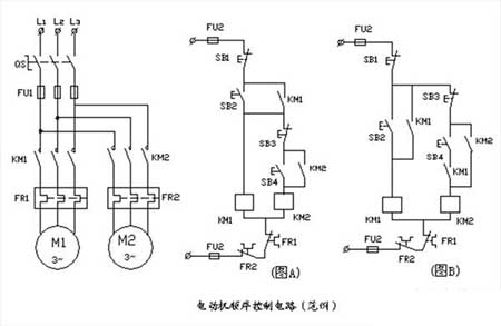
2, sequential control circuit (example)
The sequence control circuit (example) works:
The sequence control circuit (example) works:
Figure A: The KM2 coil circuit is connected after the KM1 coil circuit is started and stopped. When the start button SB2 is pressed, the KM1 coil is electrically attracted and self-locked, and the KM2 coil circuit can be controlled at this time. The stop button SB3 can only control the stop of the M2 motor, and the stop button SB1 is the stop button. This circuit can only start the M2 motor if it meets the conditions for starting the M1 motor first.
Figure B: The control circuit is composed of a KM1 coil circuit and a KM2 coil circuit. The KM1's moving contact is used as a control condition and is connected in series in the KM2 coil circuit. Only the KM1 coil is electrically connected, and its auxiliary group assists the closing contact to close. At this time, the KM2 coil circuit can be controlled. The stop button SB3 can only control the stop of the M2 motor, and the stop button SB1 is the stop button. This circuit can only start the M2 motor if it meets the conditions for starting the M1 motor first.
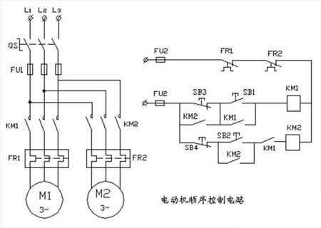
3, motor sequence control circuit
Figure B: The control circuit is composed of a KM1 coil circuit and a KM2 coil circuit. The KM1's moving contact is used as a control condition and is connected in series in the KM2 coil circuit. Only the KM1 coil is electrically connected, and its auxiliary group assists the closing contact to close. At this time, the KM2 coil circuit can be controlled. The stop button SB3 can only control the stop of the M2 motor, and the stop button SB1 is the stop button. This circuit can only start the M2 motor if it meets the conditions for starting the M1 motor first.
3, motor sequence control circuit
Description:
1. The starting sequence of this circuit is the first M1 motor and the rear M2 motor; the stopping sequence is reversed.
2. PLC (Mitsubishi FX0N, FX1N), programmer connection and power-on operation.
3, Clear operation
Program write operation; write out the instruction list according to the ladder diagram.
4. Connect the motor to the main sequence control on the main unit.
The working principle of the motor sequence control circuit: close the power switch QS, press the start button SB1, the contactor KM1 is electrically attracted and self-protected, and the M1 motor starts running. The other moving contact of the KM1 is closed to prepare the contactor KM2 for power. When the start button SB2 is pressed, the contactor KM2 is energized and self-protected, and the M2 motor is started. The starting sequence is the first KM1 pull-in, and the M1 motor starts running; After the KM2 pulls in, the M2 motor starts running. The parking sequence is:
Only when the button SB4 is pressed first, the contactor KM2 is powered off, the KM2's moving contact is opened, and the M2 motor stops and then presses SB3 to stop the M1 motor. Thermal relays FR1, FR2 normally closed contacts, the control circuit is automatically disconnected when the motor is overloaded or phase loss is overheated, and the motor is protected.


