Function of Overload Protection Switch

What is an overload protection switch?
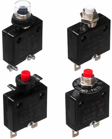
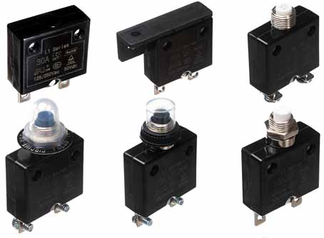
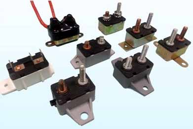
The overload protection switch is bimetallic strip overload protector to prevent the main power line from being overheated and damaged due to overload. Also called a circuit breaker. Brands are: furnas, siemens, KUOYUH.
Overload is a relatively broad term that can refer to the overload of electrical equipment (compressors, refrigerators, induction motors). The protection for these behaviors that exceed the "load" is collectively referred to as overload protection.
In the communication power system, the function of automatically disconnecting the power supply due to excessive load is called self-reset overload cut-off protection.
Introduction to overload
The amount of current that is allowed to pass continuously in an electrical circuit without overheating the wire is called safe current carrying capacity or safe current. If the current flowing through the wire exceeds the safe carrying capacity, it is called a wire overload. Generally, the maximum allowable working temperature of a wire is 65°C. When overloaded, the temperature exceeds this temperature, which will cause the insulation to rapidly age and even burn the circuit.
In machinery, when the shaft exceeds the load it can bear, overload protection can prevent equipment damage caused by overload.
In microelectronics, when the current somewhere in the circuit is too large, the overload protection can automatically cut off the power or automatically switch the working mode.

The main cause of overload
The main reason for the overload is improper selection of the wire cross section, and the actual load has exceeded the safe current of the wire;
There is also the phenomenon of "small horse-drawn carts", that is, too many high-power equipment is connected to the line, which exceeds the load capacity of the distribution line.
In important electric motors, refrigerators, air conditioners and lighting circuits in public buildings, which may cause long-term overload of wires or cables, overload protection should be adopted. The overload protection of the circuit should adopt automatic overload switch. During operation, the long-time delay action setting current of the automatic overload switch should not be greater than the long-term allowable load current of the line. If a fuse is used for overload protection, the rated current of the fuse melt should not be greater than the long-term load current of the line. When an automatic overload switch is used as a protection device, its current release should be installed on the phase line; In the three-phase four-wire system where the neutral point is not grounded, it is allowed to install on two-phase; In the ungrounded two-phase two-wire system, it is allowed to install on one phase.
Application design of overload protection
In the field of communication power supply, an overload protection switch and a current fuse are usually designed to achieve the overload protection function. Place an overload protection switch or fuse in the power supply line to achieve the overload protection function. The two devices are implemented in different ways:
Overload protection switch: When the current flowing through the load protection switch is greater than its rated current, the overload protection switch will automatically trip. The overload protection switch can be reused, and the overload protection switch can be reused after it is tripped and closed again.
Fuse: When the current flowing through the fuse is greater than its rated current, the fuse will open. The fuse is a disposable device and cannot be used again after it is blown.

Motor overload protection switch
The speed of the motor is changed by changing the winding connection, that is to say, the rotation speed of the motor is changed by changing the number of pole pairs of the rotating magnetic field of the motor.
Two-speed motor (fan), usually rotates at low speed, sometimes the fan rotates at high speed. It is mainly achieved by changing the winding connection mode of the motor coils by switching the following external control circuits.
1. Two common windings with different pole pairs are embedded in the stator slot. Change the connection of the stator winding of the motor by switching the external control circuit to realize the change of the number of magnetic pole pairs;
2. Two independent windings with different pole pairs are embedded in the stator slot;
3. Two independent windings with different pole pairs are embedded in the stator slot, and each winding can have different connections.


