The Function and Application of Energy Regulator Switch
What is the energy regulator switch?
Energy regulators (Simmerstats) - also known as energy regulators or stepless switches - are responsible for switching the heating elements in hobs, grills and various other cooking appliances on and off. During the cooking time, the Energy regulators requests the heating element to be switched on and off at regular intervals. The length of these intervals is determined by you, the user - you simply turn the control knob connected to the Simmerstat to determine how long each on and each off period should last (and thus how much energy the heating element should consume) .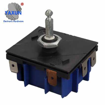
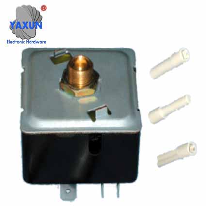
ENERGY REGULATORS switch
Yaxun's Energy regulators switch controls by periodically turning the power on and off, the relationship between on time and total time determines the average power input.Compared to a variable resistor, the switch for Energy regulators is generally cheaper, much less bulky, and applicable to any load up to its rated capacity. Furthermore, the control is effected without the energy loss associated with resistance control, is continuously variable from no load to full load, and is substantially independent of mains voltage fluctuations up to about 20%.
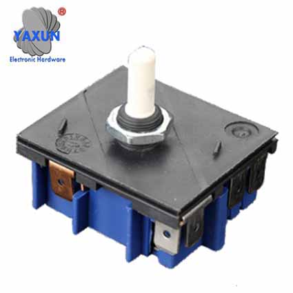
Functional description of the Energy regulator switch (simmerstat)
The switch for Energy regulators (simmerstat) mainly consists of a heated bimetal and a snap-action switch (spring contact). Fig. 1 below will clarify the mode of operation.It is a bimetallic strip support that has a cam follower whose function is to compensate for variations in ambient temperature.
It is a bimetallic strip that carries a wound heater.
It is a snap-action switch that operates the contact
It is a cutting edge on which the bimetallic assembly can pivot.
It is a means of adjustment
Normally, contact D is closed so that current flows through the heater winding on the bimetal and through the load. The bimetal heats up and, when bending, opens switch C, interrupting current to both the heater winding and the load.
The bimetal is then cooled and the cycle is repeated. The relationship between the time during which the contacts are made and the total cycle time determines the average input.
This relationship is controlled by the adjusting cam F. Clearly, if the cam is configured so that the contacts remain closed with the maximum deflection of the bimetal, the power will be on permanently; if the cam is turned until contact D opens with the cold bimetallic, the power will be permanently shut off. Between these two limits, the input is continuously adjustable.
Since the same voltage is applied to the power regulators that is applied to the load, any variation will affect the two similarly, so that the average input is independent of the applied voltage over a wide range.
Technical Specifications of Energy Regulators
| LINE INPUT | 230V + 20%, Single phase, 50Hz, 1kw Max, up to 3Kw for 3 hours Max. Can supply as per customer’s input specification |
| RANGE | 6% TO 85% adjustable |
| TEMPERATURE | Can adjust temperature up to 300 degree centigrade by dial setting |
| ISOLATION | 2.5kv A.C, for 1 minute, leakage current <3.5mA |
| LERAKAGE CURRENT | less than 210 micro Amp. As per IS 302 |
| OPERATING TEMPERATURE | 0 to 50 degree Centigrade |
| LIFE | 1,00,000 switching cycles under normal conditions |
| EMC | CE Marked |
| DIMENSIONS | Length - 50mm width - 41mm height - 74mm approx. |
| WEIGHT | 110gm approx. without dial plate |
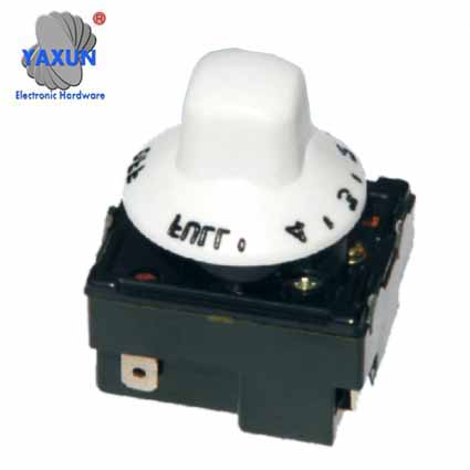
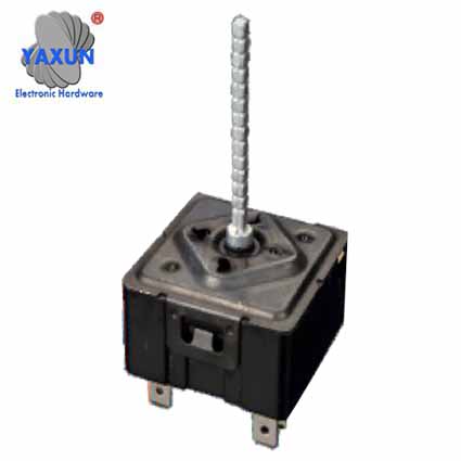
Energy Regulator Switch Features
Long duty cycle and short warm-up intervals = higher average performance, p. Eg to heatShort duty cycle and long warm-up intervals = lower average performance, p. Eg to simmer
The load output can be set between 6% and 85% of the nominal output. Select the highest setting for the full nominal rating (100%).
Infinitely variable control of power supply
Energy Regulator Switch Electrical Wiring Diagram
Energy Regulator Switch ApplicationThe energy regulator control switch is economically and conveniently applied to an extremely wide range of process heating appliances that replace a resistor or potentiometer.
In devices where it is inconvenient or impossible to install any type of thermostat, eg. Eg hot plates, injection molding nozzles, molding patterns, etc.
For small high temperature furnaces and furnaces where temperature control costs would be excessive.
For any heating process where temperature is a function of energy input only.
Controlling the rate of temperature change in a furnace in order to reduce the temperature differential or spread allowed by conventional temperature controllers.
To control entry into an oven for rapid heating without undue overheating at operating temperature.
To control the average output of a motor driving, for example, a conveyor or a pump where there is no objection to the motor starting and stopping periodically, e.g. Eg a pump that fills a tank, a motor that drives an automatic feeder or a belt that runs through a furnace.
INFINITE CONTROL SWITCH / HEAT SWITCH
Infinity Control Switch / Heat Switch provides infinite control / heat switch for non-inductive loads up to 15 amps at 120 or 240 V-AC (cannot be used with an external contactor). It can be turned left or right to adjust the proper heat from 0 to 100% power with an infinity control switch over the first 50% of full power. Energized continuously in the HI position, in other configurations it delivers the selected input level under the control of a simple bimetallic timer. Only 3 mounting holes are required to install the INFINITE HEAT / CONTROL SWITCH in the customer supplied box or panel. It is designed to be used in ambient temperatures up to 85 ° C.Infinity control switch / heat switch functional description:
The INF model rotates clockwise or counterclockwise. A dual line disconnect is provided when the control is in the "Off" position. Permanent magnet provides fast contact action. Clean marks and breaks ensure a long service life for fine silver contacts. The switch control is environmentally compensated. It is designed to operate where the ambient temperature does not exceed 85 ° C. The control contains a bimetal, which regulates the operating cycles. This bimetal has a resistance wire wrapped around it, which is connected in parallel with the heating unit that is controlled and cycles in unison with the heating element. When the switch is turned to the "ON" position, the follower moves and allows the contacts to close. This completes a circuit through a heating unit that is controlled, and also to the resistance wire wound around the bimetal. At this time, the steel armature is under the influence of the magnetic attraction of the magnet. As the resistance wire heats the bimetal, the bimetal flexes and forces build up on it. When the accumulated force equals the magnetic attraction of the magnet, the contacts click open and the steel armature moves away from the magnetic field. This opens the contacts, which will cut power to the heating unit being controlled and also disconnect power from the bimetallic resistor wire. As the bimetal cools, it will flex in the opposite direction and the contacts will begin to move closer together. At a certain point, the magnetic pull will close with a quick action. This will allow current to flow through the unit once more when the circuit is complete. A second bimetal is used as a room temperature compensator to neutralize the effect of surrounding temperatures on the control bimetal. These controls are designed to operate in locations where the maximum ambient temperature does not exceed approximately 85 ° C. The infinity control switch can control any resistive load up to 15 amps.
It is possible to get a range of inputs to the element and / or load from approximately 5% low to 100% high, and infinite settings in between.


