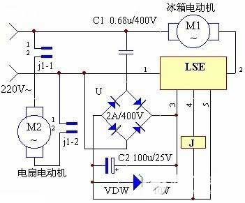
Refrigerator air-cooled synchronous temperature controller circuit diagram
Keywords: refrigerator circuit diagram temperature control circuit
The circuit operation principle of the device is shown in the figure.
Experiments show that when refrigeratory compressor is working, air-cooling measures are taken for the compressor and radiator of the refrigerator, which may not only protect the compressor, but also have obvious energy-saving effect.
When the refrigerator motor M1 start, LSE's main circuit ①, ② feet between collusion. Its 4 feet output high level, relay J excitation pull. The normally open contacts j1-1, j-2 are closed, the power of the fan M2 is turned on, and the M2 works for air cooling.
When M1 stops working, LSE's ④ feet and goes low, it is automatically released J, M2 stop working.


