TL431 Variable Voltage Dividing and Voltage Regulating Temperature Control Integrated Circuit
Keywords: temperature control circuit TL431
1. Working principle
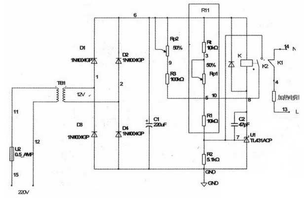
After the power is turned on, the heating resistor is connected to the 220V AC circuit through the normally closed contact of the relay, and heating begins. At this time, the temperature is normal temperature, and the thermistor of the negative temperature coefficient is 10 kΩ. As the heating progresses, the resistance of Rt continues to decrease, and Uref begins to rise. At this time, adjusting Rpl can also change the upper temperature control point T1 that determines the temperature.
When the temperature reaches the temperature control point. Rt=Rtl, Uref=UCC*R2/(R2+R11)2.5V, the output of the operational amplifier is high, the internal triode is turned on, and the relay is connected. The normally closed contact opens and the heating stops. At the same time, another set of normally open contacts of the relay is closed, so that Rp2+R3 is connected in parallel with R11 to further increase Uref. This circuit is a simple hysteresis circuit.
The lower temperature control point T2 of the thermostat can be adjusted by adjusting Rp2. As the heating stops, the temperature begins to slowly fall back. Rt gradually increases, that is, when Rt = Rtl. Due to the connection of the Rp2+R3 parallel circuit. Uref is still greater than 2.5V, the output transistor continues to conduct, maintaining the relay in the pull-in state, and the heating resistor is still in the power-off state. Only when the temperature drops to the lower temperature threshold T2. Rt=Rt2, Uref=Uc-cxR2/(R2+RI1) “2.5V op amp output low level, internal triode cut-off, relay release. The normally open contact opens and exits the connected circuit, while the normally closed contact is reset and the heating restarts. Repeatedly, the temperature is stabilized in the range T1 to T2 by controlling the heating resistor. It was found in the experiment that even if the resistor of Rp2+R3 is not used, the circuit will not exhibit thermal oscillation (that is, the relay will continuously switch at the T1 point) because of the inertness of the heat. However, it will be more reliable after adding Rp+R3, and there is a temperature threshold range of T1~T2. This value can be adjusted by Rpl and Rp2.
2. Circuit debugging
This circuit is very simple. Because the TIA31 has a driving capability of lOOmA, it can directly drive small relays, so the board can be made with a hole plate. It is more difficult to debug the circuit. Here, the 10kΩ negative temperature coefficient thermistor for temperature measurement is used with high precision. After the circuit is turned on, heating starts. The 10kΩ temperature measuring resistor is placed in the temperature control room, and the thermometer is placed at the same time, when the temperature rises to the set upper limit temperature value Tl. Adjust Rp1. Turn on the TL431 and pull the relay. Continue to observe that when the temperature drops to the lower temperature control value T2, adjust Rp2 to make TL431 cut off and the relay to release. Due to the nonlinearity of the temperature measuring resistor, the indication of the potentiometers Rp1 and Rp2 may also be nonlinear.
Just mark a few key points.
This temperature control circuit uses only one TL431 to complete the setting and control of temperature in a range. Simple and practical, cost-effective. Ideal for students and electronics enthusiasts.
1. Working principle
After the power is turned on, the heating resistor is connected to the 220V AC circuit through the normally closed contact of the relay, and heating begins. At this time, the temperature is normal temperature, and the thermistor of the negative temperature coefficient is 10 kΩ. As the heating progresses, the resistance of Rt continues to decrease, and Uref begins to rise. At this time, adjusting Rpl can also change the upper temperature control point T1 that determines the temperature.
When the temperature reaches the temperature control point. Rt=Rtl, Uref=UCC*R2/(R2+R11)2.5V, the output of the operational amplifier is high, the internal triode is turned on, and the relay is connected. The normally closed contact opens and the heating stops. At the same time, another set of normally open contacts of the relay is closed, so that Rp2+R3 is connected in parallel with R11 to further increase Uref. This circuit is a simple hysteresis circuit.
The lower temperature control point T2 of the thermostat can be adjusted by adjusting Rp2. As the heating stops, the temperature begins to slowly fall back. Rt gradually increases, that is, when Rt = Rtl. Due to the connection of the Rp2+R3 parallel circuit. Uref is still greater than 2.5V, the output transistor continues to conduct, maintaining the relay in the pull-in state, and the heating resistor is still in the power-off state. Only when the temperature drops to the lower temperature threshold T2. Rt=Rt2, Uref=Uc-cxR2/(R2+RI1) “2.5V op amp output low level, internal triode cut-off, relay release. The normally open contact opens and exits the connected circuit, while the normally closed contact is reset and the heating restarts. Repeatedly, the temperature is stabilized in the range T1 to T2 by controlling the heating resistor. It was found in the experiment that even if the resistor of Rp2+R3 is not used, the circuit will not exhibit thermal oscillation (that is, the relay will continuously switch at the T1 point) because of the inertness of the heat. However, it will be more reliable after adding Rp+R3, and there is a temperature threshold range of T1~T2. This value can be adjusted by Rpl and Rp2.
2. Circuit debugging
This circuit is very simple. Because the TIA31 has a driving capability of lOOmA, it can directly drive small relays, so the board can be made with a hole plate. It is more difficult to debug the circuit. Here, the 10kΩ negative temperature coefficient thermistor for temperature measurement is used with high precision. After the circuit is turned on, heating starts. The 10kΩ temperature measuring resistor is placed in the temperature control room, and the thermometer is placed at the same time, when the temperature rises to the set upper limit temperature value Tl. Adjust Rp1. Turn on the TL431 and pull the relay. Continue to observe that when the temperature drops to the lower temperature control value T2, adjust Rp2 to make TL431 cut off and the relay to release. Due to the nonlinearity of the temperature measuring resistor, the indication of the potentiometers Rp1 and Rp2 may also be nonlinear.
Just mark a few key points.
This temperature control circuit uses only one TL431 to complete the setting and control of temperature in a range. Simple and practical, cost-effective. Ideal for students and electronics enthusiasts.


