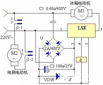
Temperature interval control circuit
Keywords: temperature control circuit 555 circuit diagram
Circuit working principle:
The 220 V mains supply is supplied to the entire circuit via transformer T step-down, VD2-VD5 bridge rectification, and C2 filtering. After the switch S is closed, since the M point potential is lower than 1/3 Vcc at this time, the 555 circuit is set. The output terminal 3 is at a high level, the relay K is pulled in, and the contact K-1 is turned on by the controlled heating circuit to increase the temperature, and the LED is instructed by the LED.


