Temperature controller can be used to control the circuit design with temperature range of -20~60°C
The temperature controller circuit uses LED light-emitting diodes to display the temperature in sections. When the temperature reaches the highest temperature displayed, the heating device automatically stops working. The temperature controller can be used to control the temperature range from -20 to 60 °C.
Temperature controller circuit diagram component selection
R1 ~ R11 and R13 ~ R15 select 1/4W metal film resistor or carbon film resistor; R12 selects 1/2W metal film resistor.
Both C1 and C2 are aluminum electrolytic capacitors with a withstand voltage of 16V.
VD1 ~ VD4 select 1N4007 type silicon rectifier diode.
VL1 ~ VL10 select φ3mm high-brightness light-emitting diodes, VL1 ~ VL9 is green, VL10 is red.
IC1 selects LM335Z type temperature sensor integrated circuit;
IC2 selects TL43l or ptA431, AS43l type three-terminal precision voltage regulator integrated circuit;
IC3 selects LM385 type voltage reference source integrated circuit;
IC4 selects LM3914 or SF3914 type LED point/line driver integrated circuit for use;
IC5 selects 78M09 type three-terminal regulator integrated circuit;
IC6 selects CD4069 or CC4069, MC14069 type six non-gate integrated circuits (the unused two non-gate inputs should be grounded).
KN selects SSP2110-1 solid state relay.
KM selects AC contactor with coil voltage of 220V, and its contact current capacity should be selected according to the actual power of EH.
T selects 6W power transformer with secondary voltage of 12V.
S uses a unipolar four-bit band switch.
Temperature controller circuit diagram circuit working principle
The temperature controller circuit is composed of a power supply circuit, a temperature detection control circuit, an LED temperature indicating circuit, and an electric heater control circuit, as shown in the figure.
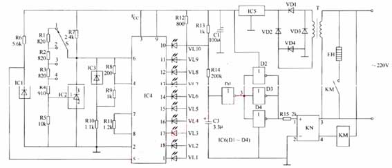
Figure Temperature controller circuit designed
The power circuit is composed of a power transformer T, rectifier diodes VD1 to VD4, a three-terminal voltage regulator integrated circuit IC5, and a filter capacitor C1.
The temperature detection control circuit is composed of a temperature sensor integrated circuit IC1, a temperature control range selection switch S, a three-terminal voltage regulation integrated circuit IC2, and resistors R1 to R6.
The LED temperature indicating circuit is composed of a voltage reference source integrated circuit IC3, an LED display driving integrated circuit IC4, resistors R8 to R13, and light emitting diodes VL1 to VL10.
The electric heater control circuit is composed of resistors R14 and R15, a capacitor C2, a non-gate integrated circuit IC6 (D1 to D4), a solid state relay KN, an AC contactor KM, and an electric heater EH.
After the AC 220V voltage is stepped down by T, VD1~VD4 rectification, IC5 voltage regulation and C1 filtering, it provides +9V working voltage for temperature detection control circuit, LED temperature indicating circuit and electric heater control circuit.
IC1 is a voltage type positive temperature coefficient integrated temperature sensor with a sensitivity of 10mY/°C. At 0 ° C, its output voltage is 2.73 V, and at 100 ° C, its output voltage is 3.73V. When the measured temperature changes, the output voltage of IC1 changes synchronously with the input voltage of pin 5 of IC4. After being processed by the 10-level voltage comparator inside IC4, VL1 to VL10 are driven to emit light, indicating the temperature value.
S has "1" (- 20 ° C ~ 0 ° C), "2" (0 ° C ~ 20 ° C), "3" (20 ° C ~ 40 ° C) and "4" (40 ° C ~ 60 ° C) four temperature control The gear position can be selected according to actual needs.
VL1 to VL10 linearly display the change in temperature with 2 ° C per segment (corresponding to a voltage of 20 mV). For example, when S is placed in the "3" range, VL1 is indicated as 22 °C, VL2 is indicated as 24 °C, VL9 is indicated as 38 °C, and VL10 is indicated as 40 °C. If both VLI and VL5 are lit during use, the measured temperature value is 30 °C.
VL1 to VL10 linearly display the change in temperature with 2 ° C per segment (corresponding to a voltage of 20 mV). For example, when S is placed in the "3" range, VL1 is indicated as 22 °C, VL2 is indicated as 24 °C, VL9 is indicated as 38 °C, and VL10 is indicated as 40 °C. If both VLI and VL5 are lit during use, the measured temperature value is 30 °C.
When the measured temperature is lower than the upper limit of the temperature control range (when VL10 is not lit), pin 10 of IC1 outputs a high level. The non-gate D1 outputs a low level, the non-gates D2 to D4 output a high level, the KN is internally turned on, the KM is pulled in, the normally open contact is turned on, and the electric heater EH is energized.
When the measured temperature reaches the upper limit of the temperature control range, VL1 to VL10 are all lit. The non-gate D1 outputs a high level, the non-gates D2 to D4 output a low level, the KN is powered off, the KM is released, the working power of the electric heater EH is cut off, and the EH stops heating.
Temperature controller circuit diagram component selection
R1 ~ R11 and R13 ~ R15 select 1/4W metal film resistor or carbon film resistor; R12 selects 1/2W metal film resistor.
Both C1 and C2 are aluminum electrolytic capacitors with a withstand voltage of 16V.
VD1 ~ VD4 select 1N4007 type silicon rectifier diode.
VL1 ~ VL10 select φ3mm high-brightness light-emitting diodes, VL1 ~ VL9 is green, VL10 is red.
IC1 selects LM335Z type temperature sensor integrated circuit;
IC2 selects TL43l or ptA431, AS43l type three-terminal precision voltage regulator integrated circuit;
IC3 selects LM385 type voltage reference source integrated circuit;
IC4 selects LM3914 or SF3914 type LED point/line driver integrated circuit for use;
IC5 selects 78M09 type three-terminal regulator integrated circuit;
IC6 selects CD4069 or CC4069, MC14069 type six non-gate integrated circuits (the unused two non-gate inputs should be grounded).
KN selects SSP2110-1 solid state relay.
KM selects AC contactor with coil voltage of 220V, and its contact current capacity should be selected according to the actual power of EH.
T selects 6W power transformer with secondary voltage of 12V.
S uses a unipolar four-bit band switch.
Temperature controller circuit diagram circuit working principle
The temperature controller circuit is composed of a power supply circuit, a temperature detection control circuit, an LED temperature indicating circuit, and an electric heater control circuit, as shown in the figure.
Figure Temperature controller circuit designed
The power circuit is composed of a power transformer T, rectifier diodes VD1 to VD4, a three-terminal voltage regulator integrated circuit IC5, and a filter capacitor C1.
The temperature detection control circuit is composed of a temperature sensor integrated circuit IC1, a temperature control range selection switch S, a three-terminal voltage regulation integrated circuit IC2, and resistors R1 to R6.
The LED temperature indicating circuit is composed of a voltage reference source integrated circuit IC3, an LED display driving integrated circuit IC4, resistors R8 to R13, and light emitting diodes VL1 to VL10.
The electric heater control circuit is composed of resistors R14 and R15, a capacitor C2, a non-gate integrated circuit IC6 (D1 to D4), a solid state relay KN, an AC contactor KM, and an electric heater EH.
After the AC 220V voltage is stepped down by T, VD1~VD4 rectification, IC5 voltage regulation and C1 filtering, it provides +9V working voltage for temperature detection control circuit, LED temperature indicating circuit and electric heater control circuit.
IC1 is a voltage type positive temperature coefficient integrated temperature sensor with a sensitivity of 10mY/°C. At 0 ° C, its output voltage is 2.73 V, and at 100 ° C, its output voltage is 3.73V. When the measured temperature changes, the output voltage of IC1 changes synchronously with the input voltage of pin 5 of IC4. After being processed by the 10-level voltage comparator inside IC4, VL1 to VL10 are driven to emit light, indicating the temperature value.
S has "1" (- 20 ° C ~ 0 ° C), "2" (0 ° C ~ 20 ° C), "3" (20 ° C ~ 40 ° C) and "4" (40 ° C ~ 60 ° C) four temperature control The gear position can be selected according to actual needs.
VL1 to VL10 linearly display the change in temperature with 2 ° C per segment (corresponding to a voltage of 20 mV). For example, when S is placed in the "3" range, VL1 is indicated as 22 °C, VL2 is indicated as 24 °C, VL9 is indicated as 38 °C, and VL10 is indicated as 40 °C. If both VLI and VL5 are lit during use, the measured temperature value is 30 °C.
VL1 to VL10 linearly display the change in temperature with 2 ° C per segment (corresponding to a voltage of 20 mV). For example, when S is placed in the "3" range, VL1 is indicated as 22 °C, VL2 is indicated as 24 °C, VL9 is indicated as 38 °C, and VL10 is indicated as 40 °C. If both VLI and VL5 are lit during use, the measured temperature value is 30 °C.
When the measured temperature is lower than the upper limit of the temperature control range (when VL10 is not lit), pin 10 of IC1 outputs a high level. The non-gate D1 outputs a low level, the non-gates D2 to D4 output a high level, the KN is internally turned on, the KM is pulled in, the normally open contact is turned on, and the electric heater EH is energized.
When the measured temperature reaches the upper limit of the temperature control range, VL1 to VL10 are all lit. The non-gate D1 outputs a high level, the non-gates D2 to D4 output a low level, the KN is powered off, the KM is released, the working power of the electric heater EH is cut off, and the EH stops heating.


