Temperature control wiring diagram and schematic design of thermostat
The principle of the temperature controller: referred to as the main temperature controller or thermostat. Feel the temperature inside the refrigerator through the end of the capillary and turn it to the corresponding pressure. When it is lower than the preset stop temperature point of the knob, the contact spring is turned over and the switch is turned off. When the temperature is higher than the preset temperature of the knob, the contact spring is turned over and the switch is turned on.
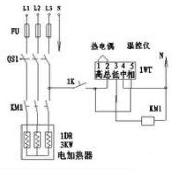
The wiring diagram and principle of the thermostat are shown in the figure. Thermocouples detect temperature. When the temperature is lower than the set value, the “total” “low” terminal is closed. The contactor is energized to turn on the heater power.
Conversely, when the temperature rises to the setting value, the “total” and “low” terminals are separated. The contactor is energized to disconnect the heater power.

The simplest control method of the thermostat is to install the temperature sensor in the control target range, and the sensor provides the temperature signal to the thermostat, and the target value can be set on the thermostat. Taking the heating control as an example, when the target value is lower than the target value, the temperature controller outputs, controls the heater at the rear end to warm the target, and stops outputting when the target value is reached.
Nowadays, many thermostats are more versatile, and there are many more detailed functions, such as PID control.
Wiring method for common temperature controller
Connected to the temperature controller, nothing more than four products: power supply, temperature sensor, temperature controller, and controller. There is a wiring diagram on each temperature control instrument. There will be a chart indicating what to pick up. Below I will briefly introduce how to wire according to the following figure.
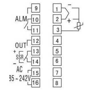
First, if you are using a thermocouple sensor, then you connect 1 and 2 terminals, 1 negative and 2 positive. If you are connected to a thermal resistor, then the normally red end is connected to terminal No. 3 and the other two are connected to 1 and 2.15 and 13 are connected by a wire, 12 is connected to the contactor, and the other end of the contactor is connected to 16 to form a circuit. 15 and 16 are connected to AC power. 9 and 10 are connected to the alarm, the wiring is to be connected with the power supply in series!
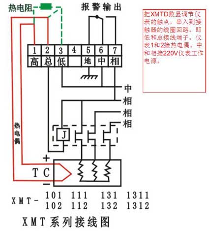
 Second, 123 is generally connected to the sensor line. 4 blank. 567 is a set of contacts, and 6 is a common point. The high total is a set of contacts, always a common point. High and always NC. Low and always NO. The ground is the instrument ground, the neutral line is the phase, and the phase is the phase line. (AC 220V power supply) The actual internal ground wire is floating, no wiring. The A2 of the contactor is connected to the neutral line, A1 is connected to the NO of the thermostat, and the com of the thermostat is connected to the live line. The zero line of the fire line enters the phase and middle of the temperature controller. There are 2 adjustment discs in front of the meter and a dial button in the middle. The adjustment disc is one high and one low, the two disc heights correspond to the rear 567, and the low ones correspond to the rear high total low. When the actual temperature changes according to the set temperature, the contact changes accordingly.

The wiring diagram and principle of the thermostat are shown in the figure. Thermocouples detect temperature. When the temperature is lower than the set value, the “total” “low” terminal is closed. The contactor is energized to turn on the heater power.
Conversely, when the temperature rises to the setting value, the “total” and “low” terminals are separated. The contactor is energized to disconnect the heater power.

The simplest control method of the thermostat is to install the temperature sensor in the control target range, and the sensor provides the temperature signal to the thermostat, and the target value can be set on the thermostat. Taking the heating control as an example, when the target value is lower than the target value, the temperature controller outputs, controls the heater at the rear end to warm the target, and stops outputting when the target value is reached.
Nowadays, many thermostats are more versatile, and there are many more detailed functions, such as PID control.
Wiring method for common temperature controller
Connected to the temperature controller, nothing more than four products: power supply, temperature sensor, temperature controller, and controller. There is a wiring diagram on each temperature control instrument. There will be a chart indicating what to pick up. Below I will briefly introduce how to wire according to the following figure.
First, if you are using a thermocouple sensor, then you connect 1 and 2 terminals, 1 negative and 2 positive. If you are connected to a thermal resistor, then the normally red end is connected to terminal No. 3 and the other two are connected to 1 and 2.15 and 13 are connected by a wire, 12 is connected to the contactor, and the other end of the contactor is connected to 16 to form a circuit. 15 and 16 are connected to AC power. 9 and 10 are connected to the alarm, the wiring is to be connected with the power supply in series!


