Five simple overheat protection circuit design schematics Detailed
This article describes five types of overheat protection devices: PTC thermistor, P-type thermal thyristor , Semiconductor thermal switch device "hot thyristor" , Thermal relay as protection device , Comparator overheat protection circuit diagram.
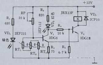
Taking the motor overheat protection as an example, the control circuit consists of a PTC thermistor and a Schmitt circuit. In the figure, RT1, RT2, and RT3 are three step-type PTC thermistors with the same characteristics, which are buried in the windings of the stator of the motor. Under normal conditions, PTC thermistors are at normal temperature and their total resistance is less than 1KΩ. At this time, V1 is turned off, V2 is turned on, and the relay K is electrically connected to the normally open contact, and the motor is operated by the commercial power supply. When the motor is partially overheated due to a fault, as long as one PTC thermistor is heated beyond the preset temperature, its resistance value will exceed 10KΩ. So V1 is turned on and V2 is cut off, VD2 shows red alarm, K is lost and released, and the motor stops running to achieve the purpose of protection.
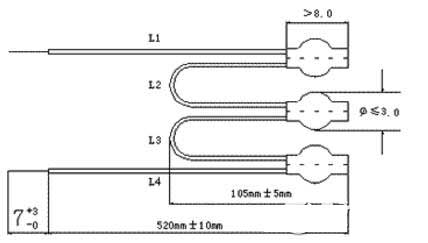
The selection of PTC thermistor for main components depends on the insulation level of the motor. The standard dimensions of the components are shown in the figure. The Curie temperature of the PTC thermistor is usually selected in a range of about 40 ° C lower than the limit temperature corresponding to the motor insulation level. For example, for a B1 insulated motor, the limit temperature is 130 ° C, and a PTC thermistor with a Curie temperature of 90 ° C should be selected. (PTC PTC thermistor for overheat protection)
 The choice of relay K depends on the capacity of the motor. Figure 2.3.1 is JRX-13F, contact load is 0.5A, suitable for small motors. The RP should be selected with a potentiometer with a locking mechanism.
 First, turn off the power, that is, after the temperature is lowered, the power supply resumes work.
Second, do not turn off the power supply, but improve the ventilation conditions inside the power supply.
Special Note: In actual design and commissioning, R1 should be placed in a device where heat should be small and heat is large.
1, the thermal shutdown circuit
 V: a stable DC voltage
Normal V&TImes; R2/(R1+R2)≤0.7V
R1: thermistor with negative temperature coefficient
C1: Take 104J63 or small-capacity aluminum electrolytic capacitor to prevent external interference
Vref: is the reference pin of the chip. 8pin such as 3842
Q1: It is just a Darlington tube for NPN. Such as 2N4401
Note: It is also possible to use an op amp, but the principle is the same. If there is an opportunity, more such circuits will be listed.
2, temperature control fan speed control circuit

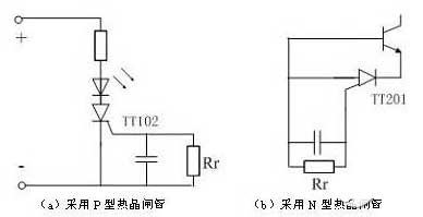
If the optocoupler is used, the whole alarm circuit can be operated to protect the switching regulator. It can also be used as an overheat protection for power transistors as in Figure 8(b). The base current of the crystal switch tube is bypassed by the n-control gate type thermal thyristor TT201, and the switch tube is turned off to cut off the collector current to prevent overheating.
(a) Using a P-type thermal thyristor (b) Using an n-type thermal thyristor
When the current increases due to overload during operation of the motor, the heat generated by the heating element of the thermal relay causes the detecting element to be bent by heat, and the normally closed contact of the thermal relay is disconnected. Cut off the power supply of the contactor, and the motor is cut off, thus playing a protective role.
The overheat protection circuit shown in Fig. 1 is composed of a temperature detecting circuit and a comparator circuit. The turn-on voltage VBE of the circuit transistor Q has a negative temperature characteristic, and the MOS transistors operating in the subthreshold region generate currents I1 and I2 having positive temperature coefficients. As the operating temperature increases, the VBE becomes smaller and smaller, and the voltage across the resistor increases with increasing current. When VBE<VR3, the comparator output is flipped, the VOUT output is low, and the main power-consuming circuit is turned off, so that the chip's heat is reduced. This overheat-protected comparator has a higher resolution and works stably at high temperatures, but it definitely increases the power consumption of the circuit. Moreover, the PTAT current proportional to the absolute temperature generated by the MOS tube operating in the subthreshold region is not high in accuracy, and is susceptible to the power supply voltage, and the overheat protection circuit is not stable enough.
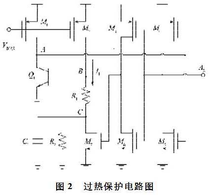
The overheat protection circuit of this paper is designed based on the bandgap reference circuit. The bias voltage of the bandgap reference circuit is used as the bias of the overheat protection circuit, and the comparator circuit is optimized in the circuit, so that the circuit structure is simple and stable, and it is easy to implement on the layout. The overheat protection circuit is shown in Figure 2.
PTC thermistor overheat protection circuit diagram (1)
Principle circuitTaking the motor overheat protection as an example, the control circuit consists of a PTC thermistor and a Schmitt circuit. In the figure, RT1, RT2, and RT3 are three step-type PTC thermistors with the same characteristics, which are buried in the windings of the stator of the motor. Under normal conditions, PTC thermistors are at normal temperature and their total resistance is less than 1KΩ. At this time, V1 is turned off, V2 is turned on, and the relay K is electrically connected to the normally open contact, and the motor is operated by the commercial power supply. When the motor is partially overheated due to a fault, as long as one PTC thermistor is heated beyond the preset temperature, its resistance value will exceed 10KΩ. So V1 is turned on and V2 is cut off, VD2 shows red alarm, K is lost and released, and the motor stops running to achieve the purpose of protection.
The selection of PTC thermistor for main components depends on the insulation level of the motor. The standard dimensions of the components are shown in the figure. The Curie temperature of the PTC thermistor is usually selected in a range of about 40 ° C lower than the limit temperature corresponding to the motor insulation level. For example, for a B1 insulated motor, the limit temperature is 130 ° C, and a PTC thermistor with a Curie temperature of 90 ° C should be selected. (PTC PTC thermistor for overheat protection)
P-type thermal thyristor overheat protection circuit diagram (2)
For high power ratings power, thermal protection is also necessary requirements. There are many types of overheat protection, commonly used circuits:Second, do not turn off the power supply, but improve the ventilation conditions inside the power supply.
Special Note: In actual design and commissioning, R1 should be placed in a device where heat should be small and heat is large.
1, the thermal shutdown circuit
Normal V&TImes; R2/(R1+R2)≤0.7V
R1: thermistor with negative temperature coefficient
C1: Take 104J63 or small-capacity aluminum electrolytic capacitor to prevent external interference
Vref: is the reference pin of the chip. 8pin such as 3842
Q1: It is just a Darlington tube for NPN. Such as 2N4401
Note: It is also possible to use an op amp, but the principle is the same. If there is an opportunity, more such circuits will be listed.
2, temperature control fan speed control circuit
Vin: is slightly larger than the maximum input voltage.
For example, if AC/DC is used, the filter capacitor is taken as normal V&TImes; R2/(R1+R2)≤0.7V
R1: thermistor with negative temperature coefficient
C1: Take 104J63 or small-capacity aluminum electrolytic capacitor to prevent external interference
Vref: Stabilizes the voltage and can use the reference pin of the chip. 8pin such as 3842
Q1: A Darlington tube that is NPN and can be overcurrent. Such as TIP31C
Note: It is also possible to use an op amp, but the principle is the same. If there is an opportunity, more such circuits will be listed.
Semiconductor thermal switch device "hot thyristor" overheat protection circuit diagram (3)
The semiconductor thermal switching device "hot thyristor" plays an important role in over-temperature protection. It can be used as a temperature indicating circuit. According to the characteristics of the p-type control gate thermal thyristor (TT102), the on-temperature of the device is determined by the value of RT [see Fig. 8(a)]. The larger the RT, the lower the on-temperature. It can be used as a temperature indicator when placed near a power switch transistor or within a power supply unit. When the temperature of the tube of the power tube or the temperature inside the device exceeds the allowable value, the thermal thyristor is turned on, causing the LED to illuminate.If the optocoupler is used, the whole alarm circuit can be operated to protect the switching regulator. It can also be used as an overheat protection for power transistors as in Figure 8(b). The base current of the crystal switch tube is bypassed by the n-control gate type thermal thyristor TT201, and the switch tube is turned off to cut off the collector current to prevent overheating.
(a) Using a P-type thermal thyristor (b) Using an n-type thermal thyristor
Figure 8 Overheat protection
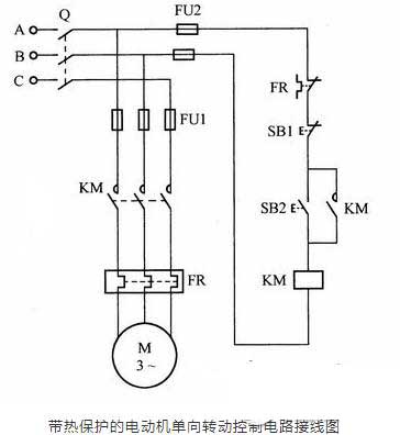
Thermal relay as protection device overheat protection circuit diagram (4)
If there is no overload protection device in the circuit, once the motor is overloaded, it is easy to burn out. The circuit shown below is a motor one-way rotation control circuit with overload protection. A thermal relay is used as a protection device in the circuit, and its heating element is connected in series in the motor circuit, and its normally closed contact is connected in series in the coil circuit of the contactor.
When the current increases due to overload during operation of the motor, the heat generated by the heating element of the thermal relay causes the detecting element to be bent by heat, and the normally closed contact of the thermal relay is disconnected. Cut off the power supply of the contactor, and the motor is cut off, thus playing a protective role.
Comparator overheat protection circuit diagram (5)
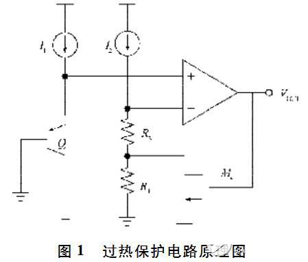
The overheat protection circuit turns off the high power tube when the chip temperature is too high, requiring high temperature sensitivity at the threshold temperature point. Therefore, most are based on comparator design. Figure 1 is a schematic diagram of an overheat protection circuit.
The overheat protection circuit shown in Fig. 1 is composed of a temperature detecting circuit and a comparator circuit. The turn-on voltage VBE of the circuit transistor Q has a negative temperature characteristic, and the MOS transistors operating in the subthreshold region generate currents I1 and I2 having positive temperature coefficients. As the operating temperature increases, the VBE becomes smaller and smaller, and the voltage across the resistor increases with increasing current. When VBE<VR3, the comparator output is flipped, the VOUT output is low, and the main power-consuming circuit is turned off, so that the chip's heat is reduced. This overheat-protected comparator has a higher resolution and works stably at high temperatures, but it definitely increases the power consumption of the circuit. Moreover, the PTAT current proportional to the absolute temperature generated by the MOS tube operating in the subthreshold region is not high in accuracy, and is susceptible to the power supply voltage, and the overheat protection circuit is not stable enough.
The overheat protection circuit of this paper is designed based on the bandgap reference circuit. The bias voltage of the bandgap reference circuit is used as the bias of the overheat protection circuit, and the comparator circuit is optimized in the circuit, so that the circuit structure is simple and stable, and it is easy to implement on the layout. The overheat protection circuit is shown in Figure 2.


