Circuit Design and Common Troubleshooting of Temperature Control Switch for Electric Blanket
This temperature control switch is the "Sun brand AC220V thermostat" produced by Korea Daming Electric Co., Ltd., which is an earlier product. Connect the 60w bulb for the dummy load test. The output voltage between H1-H2 is 90V~220V. R1 and C1 are thyristor protection circuits, and C2, D1, D2 and R4 form a zero-crossing detection circuit. This thermostat does not actually have an automatic thermostat function, and the resistor R5 connected between the output terminals S1 to S2 is useless. Therefore, this thermostat can also be directly applied to domestic electric blankets.
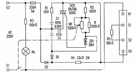
The original output terminal is connected to the 220V60W bulb dummy load test. The highest temperature state is max=50V and max=120V. In order to use domestic electric blankets, we must try to increase the output voltage. Adjust the internal trimmer potentiometer to 0Ω (the highest temperature state), the output voltage Vmax=80V, max=190V, and the output voltage is still lower. Try to connect a resistor of 1kΩ on 1R7, and the output voltage rises to Vmax=90V, max=215V. At this point the bulb is very bright, the color of the filament is dazzling white, and the brightness is almost the same as that connected to the 220V line. Re-connected domestic double electric blanket (DC resistance is 800Ω) test, normal heating in 5 minutes, the conversion was successful.
Then connected to the domestic single electric blanket (DC resistance is 1kΩ) test, the temperature is also slow in the highest temperature state, and is always in the low temperature state, because the resistance is too large and the power is too small, the high temperature function is missing. The real reason for the lack of high temperature function is that the 215V voltage output from the thermostat is not pure AC voltage. It is a half-wave AC voltage superimposed on a 90V DC voltage, that is, an AC voltage, and has a directional, one-way conduction, and the estimated AC voltage is about 120V to 150V. It is also possible to use a load with a low resistance. The output power of the high-resistance load is greatly reduced. To solve this problem, install a high and low temperature switch. When high temperature is required, the electric blanket is directly connected to the 220V power supply, and the electric blanket is heated quickly, and the temperature is not adjustable; When the low temperature gear is selected, the temperature controller works to adjust the temperature. High and low circuits are also suitable for double electric blankets. If the electric blanket resistance is around 500 Ω, high and low temperature switches are not required.
The original thermostat has a constant temperature function. There is no constant temperature function after using the domestic electric blanket, but it is better than the domestic electric blanket only the high and low second gear fixed temperature control effect. And it eliminates the situation that the domestic electric blanket can't be adjusted when it is in the low temperature block, which is uncomfortable due to overheating.
The circuit of the thermostat change is shown in the dotted line and the picture &TImes;
First, the working principle of the circuit
The circuit principle is shown in Figure 1.
When the temperature is low, the resistance coefficient of the negative temperature coefficient thermistor Rt is large, and the potential of the 2 pin of the 555 time base integrated circuit (IC) is lower than 1/3 of the Ec voltage (about 4V). The 3 pin of the IC outputs a high level, triggers the bidirectional thyristor V to conduct, and turns on the electric heater RL for heating, thereby starting the timing cycle. When the temperature of the thermistor Rt placed at the temperature measuring point is higher than the set value and the timing cycle has not been completed, the heater RL is cut off after the end of the timing period. When the thermistor Rt temperature drops below the set value, the triac V is turned on again, and the electric heater RL is turned on for heating. This will achieve the purpose of automatic temperature control.
II. Selection of components
In the circuit, the thermistor Rt can be of the MF12 type or the MF53 type with a negative temperature coefficient, and different resistance values and other types of negative temperature coefficient thermistors can be selected. As long as the relationship of Rt + VR1 = 2R4 is satisfied under the temperature conditions required to be controlled. The larger the potentiometer VR1 can achieve a larger adjustment range, but the sensitivity will decrease. The triac V can also be selected according to the magnitude of the load current. There are no special requirements for other components, and parameters are selected according to the circuit diagram.
III. Production and debugging methods
The whole circuit can be installed on a circuit board, generally no debugging is required, and the time interval is 1.1R2 & TImes; C3 should be chosen to be smaller than the thermal time constant of the heating system, but it should not be too small, otherwise it will cause excessive radio frequency interference due to the rapid turn-on or turn-off of the triac V. After installation and commissioning, it can be loaded into a small plastic box and the thermistor Rt can be taken out to the temperature measurement point.
Temperature controller circuit diagram
 Component selection
R1 ~ RIO select 1/4W metal film resistor or carbon film resistor, R2 and R3 should be ±1%. Linear potentiometers are used for RP1 to RP3. Both C1 and C2 use aluminum electrolytic capacitors with a withstand voltage of 25V; C3 uses monolithic capacitors or polyester capacitors. YD selects 1N4001 or 1N4007 silicon rectifier diode for use. VS selects 1V, 6V silicon steady voltage diode, such as 1N4735 and other models. VL1 and VL2 select φ5mm light-emitting diodes, VL1 is red, and VL2 is green. UR selects 1A, 50V rectifier bridge stack, and can also be replaced by 4 1N4001 bridges. V1 selects MTS-102 transistor type temperature sensor (can also be replaced by negative temperature coefficient thermistor); V2 selects S8550 or 3CG8550 silicon PNP transistor. IC1 selects LM324 type four operational amplifier integrated circuit; IC2 selects 7809 type three-terminal regulator integrated circuit. K selects JRX-13F type 9V DC relay. KM selects AC contactor with coil voltage of 220V, and its contact current capacity should be selected according to the actual power of EH. PV uses a 100mV voltmeter. T selects a power transformer with 3 to 5W and a secondary voltage of 12V. S selects 5A, 220V AC power switch. The power of the EH should be selected according to the actual application.
The thermostat is physically deformed inside the switch according to the temperature change of the working environment, thereby generating some special effects and generating a series of automatic control elements for conducting or breaking. Or the electronic components can provide temperature data to the circuit at different temperatures and different working states for the circuit to collect temperature data.
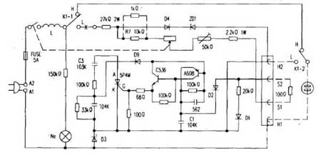
Stepless adjustment electric blanket temperature controller circuit (2)
The thermostat can steplessly adjust the temperature of the electric blanket, and the performance is excellent, and the control output power is 100W. It is a pity to discard it. The modified electric circuit can be used with the domestic electric blanket.The original output terminal is connected to the 220V60W bulb dummy load test. The highest temperature state is max=50V and max=120V. In order to use domestic electric blankets, we must try to increase the output voltage. Adjust the internal trimmer potentiometer to 0Ω (the highest temperature state), the output voltage Vmax=80V, max=190V, and the output voltage is still lower. Try to connect a resistor of 1kΩ on 1R7, and the output voltage rises to Vmax=90V, max=215V. At this point the bulb is very bright, the color of the filament is dazzling white, and the brightness is almost the same as that connected to the 220V line. Re-connected domestic double electric blanket (DC resistance is 800Ω) test, normal heating in 5 minutes, the conversion was successful.
Then connected to the domestic single electric blanket (DC resistance is 1kΩ) test, the temperature is also slow in the highest temperature state, and is always in the low temperature state, because the resistance is too large and the power is too small, the high temperature function is missing. The real reason for the lack of high temperature function is that the 215V voltage output from the thermostat is not pure AC voltage. It is a half-wave AC voltage superimposed on a 90V DC voltage, that is, an AC voltage, and has a directional, one-way conduction, and the estimated AC voltage is about 120V to 150V. It is also possible to use a load with a low resistance. The output power of the high-resistance load is greatly reduced. To solve this problem, install a high and low temperature switch. When high temperature is required, the electric blanket is directly connected to the 220V power supply, and the electric blanket is heated quickly, and the temperature is not adjustable; When the low temperature gear is selected, the temperature controller works to adjust the temperature. High and low circuits are also suitable for double electric blankets. If the electric blanket resistance is around 500 Ω, high and low temperature switches are not required.
The original thermostat has a constant temperature function. There is no constant temperature function after using the domestic electric blanket, but it is better than the domestic electric blanket only the high and low second gear fixed temperature control effect. And it eliminates the situation that the domestic electric blanket can't be adjusted when it is in the low temperature block, which is uncomfortable due to overheating.
The circuit of the thermostat change is shown in the dotted line and the picture &TImes;
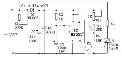
555 time base integrated electric blanket thermostat circuit (3)
This circuit is a temperature automatic controller consisting of a 555 time base integrated circuit and few peripheral components. Because the voltages at various points in the circuit are from the same DC power supply, there is no need for a regulated power supply with good performance, and the capacitor step-down method can work reliably. Circuit components are low in price, small in size, and easy to make in amateur conditions. The temperature automatic controller made by this circuit can be used for industrial heating and electric heating control of households with good effect.First, the working principle of the circuit
The circuit principle is shown in Figure 1.
Figure 1 Simple temperature controller circuit diagram using 555 time base circuit
When the temperature is low, the resistance coefficient of the negative temperature coefficient thermistor Rt is large, and the potential of the 2 pin of the 555 time base integrated circuit (IC) is lower than 1/3 of the Ec voltage (about 4V). The 3 pin of the IC outputs a high level, triggers the bidirectional thyristor V to conduct, and turns on the electric heater RL for heating, thereby starting the timing cycle. When the temperature of the thermistor Rt placed at the temperature measuring point is higher than the set value and the timing cycle has not been completed, the heater RL is cut off after the end of the timing period. When the thermistor Rt temperature drops below the set value, the triac V is turned on again, and the electric heater RL is turned on for heating. This will achieve the purpose of automatic temperature control.
II. Selection of components
In the circuit, the thermistor Rt can be of the MF12 type or the MF53 type with a negative temperature coefficient, and different resistance values and other types of negative temperature coefficient thermistors can be selected. As long as the relationship of Rt + VR1 = 2R4 is satisfied under the temperature conditions required to be controlled. The larger the potentiometer VR1 can achieve a larger adjustment range, but the sensitivity will decrease. The triac V can also be selected according to the magnitude of the load current. There are no special requirements for other components, and parameters are selected according to the circuit diagram.
III. Production and debugging methods
The whole circuit can be installed on a circuit board, generally no debugging is required, and the time interval is 1.1R2 & TImes; C3 should be chosen to be smaller than the thermal time constant of the heating system, but it should not be too small, otherwise it will cause excessive radio frequency interference due to the rapid turn-on or turn-off of the triac V. After installation and commissioning, it can be loaded into a small plastic box and the thermistor Rt can be taken out to the temperature measurement point.
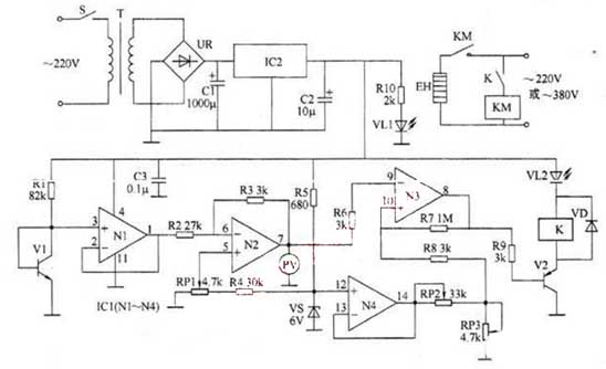
Electric blanket thermostat circuit (4)
The temperature control circuit diagram of this temperature controller has a temperature control range of 5 to 95 ° C and can be widely used for automatic temperature control in industrial production and scientific research.Temperature controller circuit diagram
R1 ~ RIO select 1/4W metal film resistor or carbon film resistor, R2 and R3 should be ±1%. Linear potentiometers are used for RP1 to RP3. Both C1 and C2 use aluminum electrolytic capacitors with a withstand voltage of 25V; C3 uses monolithic capacitors or polyester capacitors. YD selects 1N4001 or 1N4007 silicon rectifier diode for use. VS selects 1V, 6V silicon steady voltage diode, such as 1N4735 and other models. VL1 and VL2 select φ5mm light-emitting diodes, VL1 is red, and VL2 is green. UR selects 1A, 50V rectifier bridge stack, and can also be replaced by 4 1N4001 bridges. V1 selects MTS-102 transistor type temperature sensor (can also be replaced by negative temperature coefficient thermistor); V2 selects S8550 or 3CG8550 silicon PNP transistor. IC1 selects LM324 type four operational amplifier integrated circuit; IC2 selects 7809 type three-terminal regulator integrated circuit. K selects JRX-13F type 9V DC relay. KM selects AC contactor with coil voltage of 220V, and its contact current capacity should be selected according to the actual power of EH. PV uses a 100mV voltmeter. T selects a power transformer with 3 to 5W and a secondary voltage of 12V. S selects 5A, 220V AC power switch. The power of the EH should be selected according to the actual application.
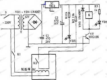
Automatic adjustment of electric blanket thermostat circuit (5)
The fluid media temperature controller is automatically adjusted by the principle of thermal expansion and contraction of the temperature sensitive fluid and the incompressibility of the liquid.The thermostat is physically deformed inside the switch according to the temperature change of the working environment, thereby generating some special effects and generating a series of automatic control elements for conducting or breaking. Or the electronic components can provide temperature data to the circuit at different temperatures and different working states for the circuit to collect temperature data.


