A Simple PWM Temperature Control Fan Circuit Design
At present, there are commonly used heat dissipation methods such as air cooling, heat pipe and water cooling. The heat dissipation effect is based on water cooling, heat pipe and air cooling. Due to the complicated heat pipe and water cooling process and high cost, air cooling is generally adopted in small and medium-sized equipment. Air cooling is mainly through the use of fans, heat sinks, etc. to transfer heat to the surrounding environment (and ultimately through the air to dissipate heat), to achieve the purpose of heat dissipation. The advantage of air cooling is that the structure is simple, the price is low (compared with other heat dissipation methods), safe and reliable, and the technology is mature. The disadvantages are noise, fan life, and time constraints. Nowadays, air-cooled products are used in the market. Generally, the cooling fan basically runs when it is turned on, and it runs at high speed during the whole process of starting up. In fact, most devices have the characteristics of intermittent work or load changes. When the load is not connected or the load is easy, the fan may not need to work or work at full speed. The heat sink can be met only by the heat sink or the fan running at low speed. Although some devices have taken this into account, the temperature switching circuit has been added. When a certain temperature is reached, the fan runs at full speed, and when it is below a certain temperature, the fan stops. Although it partially solves the problem that the fan is idling and reducing the noise, it is too simple and cannot effectively solve the problem of temperature and fan speed.
In order to effectively solve the heat dissipation problem and minimize the unnecessary operation of the cooling fan, this paper designs a temperature control circuit based on the PWM speed regulation principle. The circuit uses a NE555 time-base integrated circuit to generate a triangular modulated wave, and the NTC negative temperature coefficient thermistor generates a modulated voltage signal that varies with temperature. The triangular wave and the modulating voltage generate a pulse width modulated PWM pulse width modulated wave through the comparator. The MOS power tube is then driven to control the speed of the fan to achieve continuous adjustment of the fan speed. The principle is shown in Figure 1.
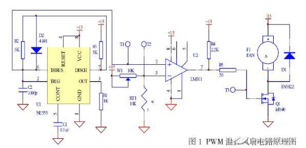
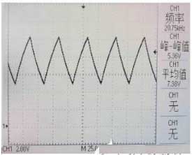
In the figure, a triangular wave generating circuit is composed of U1 (NE555), D2, R2, R3, and C2. The frequency of the triangular wave is determined by the values of R2, R3 and C2. According to the parameters in the figure, the oscillation frequency is about 20KHz. The waveform measured at test point T1 is shown in Figure 2.
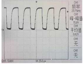
The PWM pulse width modulation wave is generated by the single-chip comparator Figure 1 PWM temperature control fan circuit schematic U2 (LM311). The triangular wave signal enters the positive input pin of the comparator, and the temperature-converted modulation voltage signal enters the negative input pin of the comparator, so that the PWM square wave is obtained at the 7th pin of U2 as shown in FIG. According to the voltage value of the top angle and the bottom angle of the triangle wave, the voltage dividing circuit of the temperature resistor can be designed to complete the relationship between the temperature and the PWM duty ratio (corresponding to the fan speed). In the figure, the potentiometer W1 is used to adjust the resistance division ratio to change the relationship between temperature and speed.
In this paper, several simple components are used to control the speed of the cooling fan, which avoids unnecessary rotation of the fan at low temperature and effectively reduces unnecessary running noise. The circuit has low cost and simple structure and has been successfully applied.
In order to effectively solve the heat dissipation problem and minimize the unnecessary operation of the cooling fan, this paper designs a temperature control circuit based on the PWM speed regulation principle. The circuit uses a NE555 time-base integrated circuit to generate a triangular modulated wave, and the NTC negative temperature coefficient thermistor generates a modulated voltage signal that varies with temperature. The triangular wave and the modulating voltage generate a pulse width modulated PWM pulse width modulated wave through the comparator. The MOS power tube is then driven to control the speed of the fan to achieve continuous adjustment of the fan speed. The principle is shown in Figure 1.
In the figure, a triangular wave generating circuit is composed of U1 (NE555), D2, R2, R3, and C2. The frequency of the triangular wave is determined by the values of R2, R3 and C2. According to the parameters in the figure, the oscillation frequency is about 20KHz. The waveform measured at test point T1 is shown in Figure 2.
The circuit composed of the potentiometer W1 and the thermistor RT1 in Fig. 1 realizes the temperature-to-voltage conversion, and the voltage at the test point T2 is obtained by the resistance division principle. From the parameter table of the 10KNTC thermistor, the corresponding voltage value at each temperature value can be calculated, and the relationship between voltage and temperature can be obtained.
The PWM pulse width modulation wave is generated by the single-chip comparator Figure 1 PWM temperature control fan circuit schematic U2 (LM311). The triangular wave signal enters the positive input pin of the comparator, and the temperature-converted modulation voltage signal enters the negative input pin of the comparator, so that the PWM square wave is obtained at the 7th pin of U2 as shown in FIG. According to the voltage value of the top angle and the bottom angle of the triangle wave, the voltage dividing circuit of the temperature resistor can be designed to complete the relationship between the temperature and the PWM duty ratio (corresponding to the fan speed). In the figure, the potentiometer W1 is used to adjust the resistance division ratio to change the relationship between temperature and speed.
In this paper, several simple components are used to control the speed of the cooling fan, which avoids unnecessary rotation of the fan at low temperature and effectively reduces unnecessary running noise. The circuit has low cost and simple structure and has been successfully applied.


