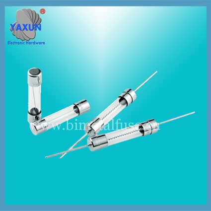
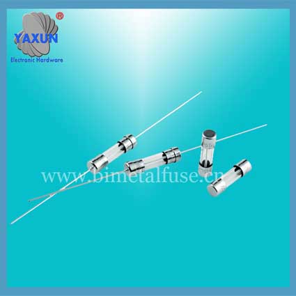
Resistance Fuse amp Interrupting Rating
- PRODUCT DETAIL
A fuse is also called a current fuse, which is defined by the IEC127 standard as a "fusible link". It is mainly used for overload protection. If the fuse is correctly placed in the circuit, the fuse will automatically cut off the current when the current abnormally rises to a certain height and heat, which protects the safe operation of the circuit.
The fuse invented by Edison more than a hundred years ago was used to protect the then expensive incandescent lamps. With the development of the times, the fuse to protect electrical equipment from overcurrent, overheating damage. Avoid serious injuries caused by internal malfunctions of electronic equipment.
How fuses work
When a current flows through the fuse conductors, conductors because there is a certain resistance, the conductor will generate heat. And the calorific value follows this formula: Q = 0.24I2RT; Where Q is the amount of heat, 0.24 is a constant, I is the current flowing through the conductor, R is the resistance of the conductor, and T is the time the current flows through the conductor; Based on this formula, it is not difficult to see the simple working principle of the fuse.
When the material and shape of the fuse are determined, its resistance R is relatively determined (if its temperature coefficient of resistance is not considered). When current flows through it, it generates heat, and its heat generation increases with time. The magnitude of the current and resistance determines the rate of heat generation. The structure of the fuse and its installation condition determine the rate of heat dissipation. If the rate of heat generation is less than the rate of heat dissipation, the fuse will not blow. If the rate of heat generation is equal to the rate of heat dissipation, it will not melt for a long time. If the rate of heat generation is greater than the rate of heat dissipation, more and more heat will be generated. And because it has a certain specific heat and mass, the increase in its heat is reflected in the increase in temperature. When the temperature rises above the fuse's melting point, the fuse will blow. This is how the fuse works. We should know from this principle that when you design and manufacture fuses, you must carefully study the physical characteristics of the materials you choose and ensure that they have a consistent geometry. Because these factors play a vital role in the normal operation of the fuse. Also, when you use it, be sure to install it correctly.
A、 Product features
Anti surge performance of the product is good, the fuse good consistency, small volume, convenient installation, safe and
reliable, widely used in electric light source, switching power supplies, chargers and home appliances and other electronic
equipment。
Two、 Size and shape
Two、 Size and shape

|
Type number
|
Rated power
W
|
Size (mm)
|
Paint root length allowed*(mm)
|
|||
|
Dmax
|
Lmax
|
H±1
|
d±0.05
|
|||
|
RXF
|
0.25、0.5S
|
3.0
|
7.0
|
60~70
|
0.38~0.45
|
≤1
|
|
0.5、1S
|
4.0
|
11
|
60~95
|
0.43~0.60
|
≤1.5
|
|
|
1、2S
|
5.0
|
12
|
60~70
|
0.54~0.72
|
||
|
2、3S
|
6.0
|
16
|
60~80
|
0.60~0.72
|
||
Three、 Technical note
General data
1、 Nominal resistance tolerance:±5%、±10%
2、 Climate category:55/155/21
3、 Low pressure:8.5kpa
4、 Stability grade:5%
5、 The resistance change limit value:
5.1、 Long term test:±(5%R+0.1Ω)
5.2、 Short term test:±(1%R+0.05Ω)
6、 Temperature coefficient:±350*10-6/℃
7、 Rated current:I2(A)=P(W)/R(Ω)
1、 Nominal resistance tolerance:±5%、±10%
2、 Climate category:55/155/21
3、 Low pressure:8.5kpa
4、 Stability grade:5%
5、 The resistance change limit value:
5.1、 Long term test:±(5%R+0.1Ω)
5.2、 Short term test:±(1%R+0.05Ω)
6、 Temperature coefficient:±350*10-6/℃
7、 Rated current:I2(A)=P(W)/R(Ω)
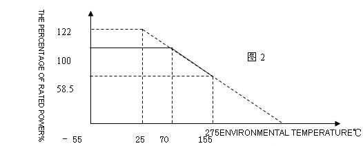
8、Power curve in Figure2:

Note: the power rating is the maximum continuous operating at 70 ℃ temperature exceeds 70 ℃, reducing power consumption by the curve。
9、Fuse characteristic
Definition: the overload of resistors impose requirements, resistance increased significantly; the current flowing through the
resistor to drop to the initial experimental current below 1/50 is called the fuse. The resistor from plus the specified overload to
fuse the time required is called the melting time. This property is called the fuse characteristics。
Requirements: overload conditions at rated current ratio rules, the melting time shall conform to the following provisions;
Table3
Requirements: overload conditions at rated current ratio rules, the melting time shall conform to the following provisions;
Table3
|
Rated current ratio (Times)
|
Fusing time(S)
|
|
|
0.25W
|
R<1Ω:6 R≥1Ω:8
|
≤30
|
|
0.5~3W
|
R<1Ω:5 R≥1Ω:6
|
≤30
|
|
Note: the melting time according to make user requirements
|
||
10、Anti shock performance
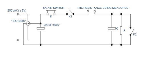
According to figure 3 switch K, turn on the switch K2, according to 1S 1S off, K1 repeated off 30 times, test the resistance should not open。



11、Surge (Surge) characteristics
Test conditions: in accordance with the standard IEC61000-4-5 test, load specific for the output end is connected with the corresponding, applying a surge voltage, waveform:1.2/50us 8/20usCombination wave; coupled mode: L-N, L N-PE, L-PE, N-PE according to the requirement of selection; polar respectively: positive and negative; phase angle: 0°、90°、180°、270°,Surge frequency 5 times each, interval time60S。
Test standard: after the test, test the resistance should not open。
12, the main test items, test methods and performance requirements (if no special instructions, are in the standard test atmospheric conditions)
Test standard: after the test, test the resistance should not open。
12, the main test items, test methods and performance requirements (if no special instructions, are in the standard test atmospheric conditions)
|
Serial number
|
Test project
|
Test method
|
Performance requirements
|
|
1
|
Resistance
|
Resistance sorting instrument measurement error.
|
Resistance value at nominal resistance and
The allowable deviation range。
|
|
2
|
Short term load
|
Rated voltage, resistor applied 2.5 times for 5S, 1 ~ 2H after recovery of the resistance measurement, and calculate the resistance change rate.
|
The resistance change:
△R≤±(2%R+0.05Ω)
|
|
3
|
Weldability
|
Slot welding method, the resistor terminations immersion(260±5)℃
The solder pot, the insertion depth distance element body2-0.5 mm
For 2± 0.5S, remove the observed solder coverage area.
|
Be immersed in the peripheral part of the direction of the surface 90% coverage。
|
|
4
|
High voltage
|
The resistor is placed in metal “ V” grooves, insulation voltage regulation, voltage and resistance in the two wire and &ldquo together; V” groove between 60S, continued.
|
No breakdown, arcing
|
|
5
|
Resistance to soldering heat
|
Before the experiment measuring resistance, the resistor terminations immersion350±10℃The solder pot, continued 3.5±0.5 S After recovery,1hAfter measuring, calculating the resistance change rate.
|
The resistance change:
△R≤±(1%R+0.05Ω)
|
|
6
|
Rapid temperature changes
|
According to the low temperature:-55±3℃,Time: 30 minutes, normal temperature, time2-3Minutes, high temperature 155± 3 ℃ , time: 30 minutes at room temperature, time, style= "2-3 minutes, this is a cycle, do 5 cycles, restore the 1-2h after measuring and calculating the resistance change rate
|
The resistance change:
△R≤±(1%R+0.05Ω)
|
|
7
|
Durability
|
The resistor is placed in the constant temperature box (70± 3) ℃, input rated DC voltage, 1.5h, 0.5h fault, so the cycle of 1000h, 1&mdash recovery after removing; after 4h, the resistance measurement, calculation of resistance change rate. The paperspan>
|
The resistance change:
△R≤±(5%R+0.1Ω)
|
|
8
|
Terminal strength
|
Pull: with 10N it continued to pull 10S; bending:In the end with5NLoad, the resistor body (2-3 "FONT-SIZE: 12pt") S in 90° after recovery, the other direction bending, namely bending 2 time.
|
The resistance change:
△R≤±(1%R+0.05Ω)。
|
|
9
|
Vibration
|
The resistor body and installation point distance of 6± 1mm, vibration rate range of 10-500HZ,: 0.75mm "FONT-SIZE: 12pt 98m/s2 "FONT-SIZE: 12pt" > the lesser of ; vibration direction and time along the Z "FONT-SIZE: 12pt", XY axis 2h "FONT-SIZE: 12pt, , cycle:1min;
(10-55-10HZ),Resistance measurement test, and calculate the resistance change rate。
|
1)Appearance: no mechanical damage
(2)The resistance change:
△R≤±(1%R+0.05Ω)
|
|
10
|
Climate sequence
|
-Dry cyclic damp heat test, Db, the first cycle cold; low pressure cyclic damp heat test cycle, Db, DC load the rest
|
The resistance change:
△R≤±(5%R+0.1Ω)
|
|
11
|
The resistance change
|
The test samples were installed in the 25± 3mm, applying 5 "FONT-SIZE: 12pt", 10 "FONT-SIZE: 12pt", 16 rated power consumption load, duration of 5min< span style= "FONT-SIZE: 12pt" > or to the resistor into open check。
|
The screen cylinder misfire
|
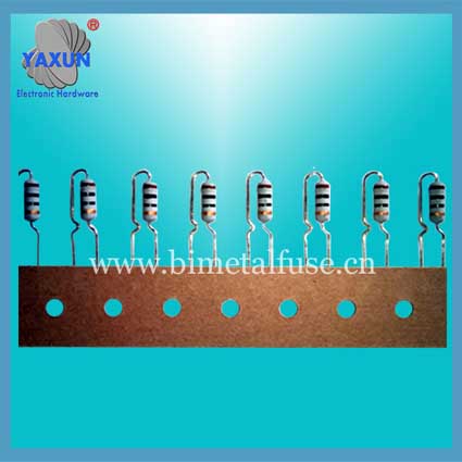
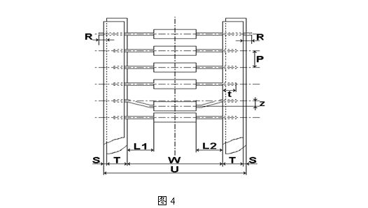
13、Braid type and size as shown in Figure 4, table5:

|
Taping specifications
|
Size (㎜)
|
||||||||
|
U
|
W
|
P
|
L1-L2
|
T
|
Z
|
R
|
t
|
S
|
|
|
T26
|
38±1
|
26±0.5
|
5±0.5
|
<0.5
|
6±0.1
|
≤1
|
0
|
≥3.2
|
<0.8
|
|
T52
|
64±2
|
52±1
|
<1
|
||||||
|
T63
|
75±2
|
63±1
|
≤1,2
|
||||||
|
75±2
|
63±1
|
10±0.5
|
|||||||
|
T72
|
84±2
|
72±2
|
5±0.5
|
<1.2
|
|||||
|
84±2
|
72±2
|
10±0.5
|
|||||||
14、Casing product style and size is shown in Figure 5, table6
|
Shape
|
inch ruler; (㎜)
|
|||||
|
H±1
|
H1±1.5
|
H2±1.5
|
h≤ h (1±5%)
|
h1±2
|
h2±2
|
|
|
TA Type
|
70
|
20
|
20
|
50
|
10
|
10
|
|
TB Type
|
80
|
5
|
25
|
40
|
10
|
30
|
|
Note: 1, the lead exposed parts≤5㎜, tolerance is +2/-1 mm, 2, casing size can be manufactured according to customer requirements
|
||||||

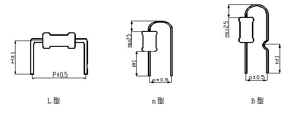
15、Molding style and size chart

|
Shape
|
Size(㎜)
|
|||
|
P±0.5
|
H±1
|
h±1
|
Note:
Shape and size can be produced according to customer requirements
|
|
|
nType
|
5
|
4
|
|
|
|
10
|
4
|
|
||
|
BType
|
5
|
|
4.5
|
|
|
10
|
|
4.5
|
||
|
LType
|
10
|
4.5
|
|
|
|
12
|
4.5
|
|
||
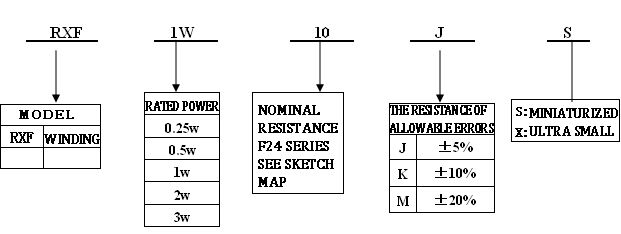
16、Specification name specification (cases)

17、Resistor color ring sign

|
Color
Color
|
First digital
First digit
|
Second digitalSecond digit
|
Third digital
Third digit
|
Multiplier
Malutiplier
|
Error rateTolerance
|
|
Black Black
|
0
|
0
|
0
|
100
|
—
|
|
Brown Brown
|
1
|
1
|
1
|
101
|
±1
|
|
Red Red
|
2
|
2
|
2
|
102
|
±2
|
|
Orange Orange
|
3
|
3
|
3
|
103
|
—
|
|
Huang Yellow
|
4
|
4
|
4
|
104
|
—
|
|
Green Green
|
5
|
5
|
5
|
105
|
±0.5
|
|
Blue Blue
|
6
|
6
|
6
|
106
|
±0.25
|
|
Purple Violet
|
7
|
7
|
7
|
107
|
±0.1
|
|
Ash Gray
|
8
|
8
|
8
|
108
|
—
|
|
White White
|
9
|
9
|
9
|
109
|
—
|
|
Gold Gold
|
—
|
—
|
—
|
10-1
|
±5
|
|
Silve rSilver
|
—
|
—
|
—
|
10-2
|
±10
|
|
no Plain
|
—
|
—
|
—
|
—
|
±20
|
Product description
● product introduction: fuse resistor (also called insurance resistor, Wirewound resistors, Wirewound resistors, fuse resistance), is a new type of special element has a dual role of resistor and fuse. It with the letter &ldquo in the circuit; RF” or “ R”
representation.
● Rated power: 1/4W, 1/2WS, 1/2W, 1WS, 1W, 2WS, 2W, 3WS etc.
● Rated power: 1/4W, 1/2WS, 1/2W, 1WS, 1W, 2WS, 2W, 3WS etc.
● withstand voltage: 350V
● resistance range: 0.1Ω ~510Ω.
● error: ± 1%~± 5%
● certification: UL/VDE/CQC certification
The product features:
● resistance range: 0.1Ω ~510Ω.
● error: ± 1%~± 5%
● certification: UL/VDE/CQC certification
The product features:
1, is the best choice for small power low cost scheme.
2, can satisfy the anti surge current shock and anti lightning requirements.
Heat dissipation capability of
3, strong, low temperature coefficient, high pressure resistance, insulation, flame retardant, explosion proof, long life.

