Waterproof ds18b20 Digital Temperature Sensor
- PRODUCT DETAIL
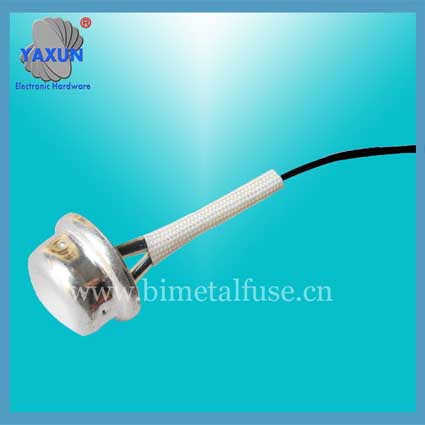
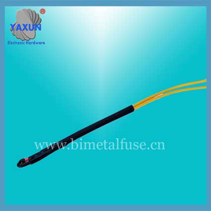
DS18B20 is a commonly used digital temperature sensor. The output is a digital signal, which has the characteristics of small size, low hardware overhead, strong anti-interference ability, and high accuracy. DS18B20 digital temperature sensor is easy to connect, and it can be applied to many occasions after being packaged, such as pipe type, screw type, magnet type, and stainless steel package type. There are various models, including LTM8877, LTM8874 and so on.
It mainly changes its appearance depending on the application. The packaged DS18B20 can be used for cable trench temperature measurement, blast furnace water circulation temperature measurement, boiler temperature measurement, machine room temperature measurement, agricultural greenhouse temperature measurement, clean room temperature measurement, ammunition depot temperature measurement and other non-limiting temperature occasions. Wear-resistant and bump-resistant, small in size, easy to use, and various packaging forms, suitable for digital temperature measurement and control of various small space equipment.
DS18B20 Temperature Data Sheet

(3) DS18B20 temperature sensor memory The internal memory of DS18B20 temperature sensor includes a high-speed temporary storage RAM and a non-volatile electrically erasable EEPRAM. The latter stores high-temperature and low-temperature triggers TH, TL, and structure registers.
(4) Configuration register The meaning of each bit of this byte is as follows:
Table 3: Configuration Register Structure
The lower five bits are always "1". TM is a test mode bit, which is used to set the DS18B20 in working mode or test mode. This bit is set to 0 when the DS18B20 is shipped from the factory. Users should not change it. R1 and R0 are used to set the resolution, as shown in the following table: (DS18B20 is set to 12 bits when shipped)
Table 4: Temperature resolution setting table
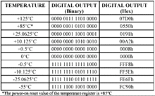
4. High-speed temporary storage memory The high-speed temporary storage memory consists of 9 bytes, and its allocation is shown in Table 5. When the temperature conversion command is issued, the converted temperature value is stored in the two-byte two's complement format in the 0th and 1st bytes of the high-speed temporary storage memory. The single-chip microcomputer can read the data through the single-line interface. When reading, the low bit is first, and the high bit is after. Corresponding temperature calculation: When the sign bit S = 0, directly convert the binary bit to decimal; When S = 1, the complement code is changed to the original code, and then the decimal value is calculated. Table 2 shows the corresponding temperature values. The ninth byte is the redundancy check byte. Table 5: DS18B20 temporary storage register distribution
According to the communication protocol of DS18B20, the host (microcontroller) must control DS18B20 to complete the temperature conversion through three steps:
Reset the DS18B20 before each read or write. After the reset is successful, a ROM command is sent, and finally a RAM command is sent, so that the DS18B20 can perform the predetermined operation.
Reset requires the main CPU to pull down the data line for 500 microseconds and then release. When the DS18B20 receives a signal, it waits for about 16 to 60 microseconds, and then issues a low pulse of 60 to 240 microseconds. The main CPU receives this signal to indicate that the reset was successful.
Table 6: ROM instruction table
Table 6: RAM instruction table
It mainly changes its appearance depending on the application. The packaged DS18B20 can be used for cable trench temperature measurement, blast furnace water circulation temperature measurement, boiler temperature measurement, machine room temperature measurement, agricultural greenhouse temperature measurement, clean room temperature measurement, ammunition depot temperature measurement and other non-limiting temperature occasions. Wear-resistant and bump-resistant, small in size, easy to use, and various packaging forms, suitable for digital temperature measurement and control of various small space equipment.
DS18B20 Temperature Data Sheet

(3) DS18B20 temperature sensor memory The internal memory of DS18B20 temperature sensor includes a high-speed temporary storage RAM and a non-volatile electrically erasable EEPRAM. The latter stores high-temperature and low-temperature triggers TH, TL, and structure registers.
(4) Configuration register The meaning of each bit of this byte is as follows:
Table 3: Configuration Register Structure
| TM | R1 | R0 | 1 | 1 | 1 | 1 | 1 |
The lower five bits are always "1". TM is a test mode bit, which is used to set the DS18B20 in working mode or test mode. This bit is set to 0 when the DS18B20 is shipped from the factory. Users should not change it. R1 and R0 are used to set the resolution, as shown in the following table: (DS18B20 is set to 12 bits when shipped)
Table 4: Temperature resolution setting table
|
4. High-speed temporary storage memory The high-speed temporary storage memory consists of 9 bytes, and its allocation is shown in Table 5. When the temperature conversion command is issued, the converted temperature value is stored in the two-byte two's complement format in the 0th and 1st bytes of the high-speed temporary storage memory. The single-chip microcomputer can read the data through the single-line interface. When reading, the low bit is first, and the high bit is after. Corresponding temperature calculation: When the sign bit S = 0, directly convert the binary bit to decimal; When S = 1, the complement code is changed to the original code, and then the decimal value is calculated. Table 2 shows the corresponding temperature values. The ninth byte is the redundancy check byte. Table 5: DS18B20 temporary storage register distribution
| Register contents | Byte address |
|
Low temperature value (LS Byte)
|
0 |
| High temperature value (MS Byte) | 1 |
| High temperature limit (TH) | 2 |
| Low temperature limit (TL) | 3 |
| Configuration register | 4 |
| Keep | 5 |
| Keep | 6 |
| Keep | 7 |
| CRC check value | 8 |
According to the communication protocol of DS18B20, the host (microcontroller) must control DS18B20 to complete the temperature conversion through three steps:
Reset the DS18B20 before each read or write. After the reset is successful, a ROM command is sent, and finally a RAM command is sent, so that the DS18B20 can perform the predetermined operation.
Reset requires the main CPU to pull down the data line for 500 microseconds and then release. When the DS18B20 receives a signal, it waits for about 16 to 60 microseconds, and then issues a low pulse of 60 to 240 microseconds. The main CPU receives this signal to indicate that the reset was successful.
Table 6: ROM instruction table
| Instruction | Convention code | Features |
| Read ROM | 33H | Read the code in the DS1820 temperature sensor ROM (ie 64-bit address) |
| ROM compliant | 55H | After issuing this command, a 64-bit ROM code is then issued to access the DS1820 corresponding to the code on the single bus to make it respond, preparing for the next reading and writing of the DS1820. |
| Search ROM | FOH | It is used to determine the number of DS1820 connected on the same bus and identify the 64-bit ROM address. Prepare for operation of each device. |
| ROM skip | CCH | Ignore the 64-bit ROM address and directly send a temperature conversion command to DS1820. Suitable for monolithic work. |
| Alarm search command | ECH | After the execution, only the films whose temperature exceeds the upper or lower limit of the set value will respond. |
Table 6: RAM instruction table
| Instruction | Convention code | Features |
| Temperature conversion | 44H | Start DS1820 for temperature conversion. The longest time is 750ms for 12-bit conversion (9.75ms for 9-bit). The result is stored in the internal 0th and 1th byte RAM. |
| Read register | BEH | Continuously read the contents of 9 bytes in the internal RAM |
| Write register | 4EH | A command to write upper and lower temperature data to the 2nd, 3rd, and 4th bytes of the internal RAM is issued. Following this command, three bytes of data are transferred. |
| Backup settings | 48H | Copy the contents of bytes 2, 3, and 4 in RAM to the EEPROM. |
| Restore settings | B8H | Restores the contents of the EEPROM to bytes 2, 3, and 4 in RAM. |
| Read power mode | B4H | Read the power mode of the DS1820. DS1820 sends "0" when parasitic power is supplied, and DS1820 sends "1" when powered by external power supply. |


