Working principle and circuit design of adjustable thermostat controller
It’s cold, and the electric blanket at home doesn’t have a constant temperature function. It can not be adjusted, and it is neither convenient nor reliable to manually control the temperature of the electric blanket. To this end, the author made an electric heating blanket adjustable thermostat controller. The electric blanket can be automatically kept within a certain temperature range, and the user can set the temperature range that is most suitable for the user. When the temperature is lower than the set lower limit temperature, the electric blanket automatically heats up, and when the temperature is higher than the set upper line temperature, the power is automatically disconnected, thereby achieving the purpose of automatic constant temperature.
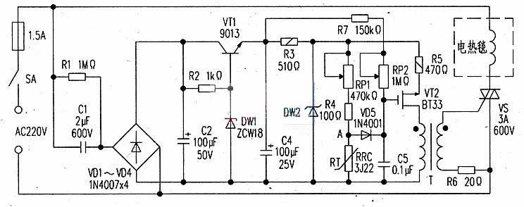 In the drawing, the pulse isolation transformer T adopts a soft ferrite magnetic ring, such as MX2000-6000, and an inner diameter of 11 mm to 18 mm, and the primary and secondary are wound with an enamel of φ0.19 mm. The remaining component parameters are as shown in the drawing and have no special requirements.
2, debugging
The components are soldered as shown in the drawing, and can be debugged after checking. During debugging, first adjust the resistance of R2 so that the current flowing through DW1 is about 10mA. At this time, the voltage across capacitor C4 is 12V. The RT is taken out with a soft temperature-resistant thin wire and hidden in the appropriate part of the electric blanket (note the insulation between the RT legs and the insulation between the RT and the heating wire, and pay attention to the protection of the RT). Only P2 will be adjusted to the minimum value. Adjust the potentiometer RP1, and cooperate with the mercury thermometer to measure the position of the RP1 when the electric blanket is between 36 °C and 42 °C. Then, according to the need to control the sensitivity, adjust RP2 to the appropriate position.
When installing, remove the electric blanket power switch, fix the adjusted circuit board in a small plastic box, and fix the RP1 on a small plastic box.
1, the working principle
The circuit is shown in the drawing. The AC220v power supply is stepped down by R1 and C1, VD1~VD4 is rectified, C2 is filtered, and then regulated by VT1, R2, DW1, C4 to DC12V, and supplied by VT2, RP1, RP2, R4, R5, RT, C5, etc. The relaxation oscillator is configured to provide a trigger pulse for the control electrode of the triac VS, and the RP1 is given a voltage (adjusted temperature), and the resistance value determines the temperature; The thermistor RT (negative temperature coefficient) is used to detect the temperature. When the power is on, the temperature of the electric blanket is low, the resistance of RT is large, the potential of point A is high, the charging time constant of C5 becomes smaller, and VT2 oscillates in advance, so that the conduction angle of the thyristor VS is advanced, and the current flowing through the electric blanket is large. Make it reach the predetermined temperature setting as soon as possible. When the temperature of the electric blanket rises, the resistance value of RT becomes smaller, the potential at point A decreases, the current flowing through the electric blanket decreases, and the temperature gradually decreases, thereby achieving automatic constant temperature.
The circuit is shown in the drawing. The AC220v power supply is stepped down by R1 and C1, VD1~VD4 is rectified, C2 is filtered, and then regulated by VT1, R2, DW1, C4 to DC12V, and supplied by VT2, RP1, RP2, R4, R5, RT, C5, etc. The relaxation oscillator is configured to provide a trigger pulse for the control electrode of the triac VS, and the RP1 is given a voltage (adjusted temperature), and the resistance value determines the temperature; The thermistor RT (negative temperature coefficient) is used to detect the temperature. When the power is on, the temperature of the electric blanket is low, the resistance of RT is large, the potential of point A is high, the charging time constant of C5 becomes smaller, and VT2 oscillates in advance, so that the conduction angle of the thyristor VS is advanced, and the current flowing through the electric blanket is large. Make it reach the predetermined temperature setting as soon as possible. When the temperature of the electric blanket rises, the resistance value of RT becomes smaller, the potential at point A decreases, the current flowing through the electric blanket decreases, and the temperature gradually decreases, thereby achieving automatic constant temperature.
2, debugging
The components are soldered as shown in the drawing, and can be debugged after checking. During debugging, first adjust the resistance of R2 so that the current flowing through DW1 is about 10mA. At this time, the voltage across capacitor C4 is 12V. The RT is taken out with a soft temperature-resistant thin wire and hidden in the appropriate part of the electric blanket (note the insulation between the RT legs and the insulation between the RT and the heating wire, and pay attention to the protection of the RT). Only P2 will be adjusted to the minimum value. Adjust the potentiometer RP1, and cooperate with the mercury thermometer to measure the position of the RP1 when the electric blanket is between 36 °C and 42 °C. Then, according to the need to control the sensitivity, adjust RP2 to the appropriate position.
When installing, remove the electric blanket power switch, fix the adjusted circuit board in a small plastic box, and fix the RP1 on a small plastic box.


