Temperature-Frequency Conversion Temperature Controller Circuit Diagram Composed of LM567 and NE555
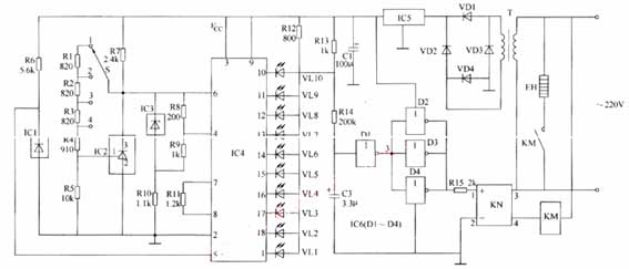
The thermostat controller consists of the thermistor Rt1, Rt2, NE555 time base circuit, temperature range adjustment resistors RP1, RP2 and the control actuator. The circuit is shown in Figure 1 (click here to download the schematic).
Rt1 and RP1 are upper limit temperature detecting resistors, and Rt2 and RP2 are lower limit temperature detecting resistors. When the temperature drops, when the potential of the 2 pin is lower than 1/3Vcc, the 3 pin outputs a high level, the J pulls in, the LED 2 lights up, and the heating starts. When the temperature rises and the IC6 pin potential is higher than 2/3Vcc, the 3 pin outputs a low level, J is released, the controlled "heater" power is turned off, and the heating is stopped.
Component selection and production
The list of components is shown in the table below.
When adjusting, it is preferred to adjust the upper limit temperature, put Rt1 in the required upper temperature environment (monitored by thermometer), after one minute (Rt1 and the environment reach thermal equilibrium). Adjust RP1 to LED1 just to emit light, repeat multiple times, you can short the 2 feet to the ground, so that the 3 feet output high level (LED1 is on), so that it is easy to observe the flip state. Then adjust the lower limit temperature, the process is the same as above, adjust RP2 to make red LED2 bright, and also adjust it several times. You can short the 6 pin to the power supply Vcc first, so that the 3 pin output low level, observe the circuit flip state.
The circuit is preferably powered by a small regulated power supply (you can choose one according to your actual power supply technology in the station).
The circuit is slightly modified to act as an ultra (high, low) temperature alarm.
Rt1 and RP1 are upper limit temperature detecting resistors, and Rt2 and RP2 are lower limit temperature detecting resistors. When the temperature drops, when the potential of the 2 pin is lower than 1/3Vcc, the 3 pin outputs a high level, the J pulls in, the LED 2 lights up, and the heating starts. When the temperature rises and the IC6 pin potential is higher than 2/3Vcc, the 3 pin outputs a low level, J is released, the controlled "heater" power is turned off, and the heating is stopped.
Component selection and production
The list of components is shown in the table below.
| Numbering | Name | Model | Quantity |
| Rt1、Rt2 |
Thermistor
|
6.8K Negative temperature coefficient | 2 |
| RP1、RP2 | Trimmer resistor | 15K | 2 |
| R3、R4 | resistance | 470Ω | 2 |
| C | Polyester capacitor | 0.01 | 1 |
| LED | Light-emitting diode | 1 green and 1 each | 2 |
| IC | Time base integrated circuit | NE555 | 1 |
| J | Electromagnetic relay | Voltage 6V current reference heater | 1 |
When adjusting, it is preferred to adjust the upper limit temperature, put Rt1 in the required upper temperature environment (monitored by thermometer), after one minute (Rt1 and the environment reach thermal equilibrium). Adjust RP1 to LED1 just to emit light, repeat multiple times, you can short the 2 feet to the ground, so that the 3 feet output high level (LED1 is on), so that it is easy to observe the flip state. Then adjust the lower limit temperature, the process is the same as above, adjust RP2 to make red LED2 bright, and also adjust it several times. You can short the 6 pin to the power supply Vcc first, so that the 3 pin output low level, observe the circuit flip state.
The circuit is preferably powered by a small regulated power supply (you can choose one according to your actual power supply technology in the station).
The circuit is slightly modified to act as an ultra (high, low) temperature alarm.


