TTS-202 Analog thermostat adjustable upper and lower temperature control
Keywords: analog temperature control TTS-202
First, the upper and lower limits of the temperature control circuit diagram
In industrial production processes, it is often necessary to control the temperature within a certain range.
If the upper limit temperature is TH and the lower limit temperature is TL, the temperature is controlled between TH and TL, as shown in Fig. 1. If the temperature exceeds TH, cooling is required to cool down; if the temperature is lower than TL, the heating is required to be measured.
TTS-202 is a temperature switch which can continuously adjust the control temperature (threshold temperature), and it is also a special one-way thyristor. Unlike a general unidirectional thyristor, it is turned on without triggering current and is temperature controlled:
When the temperature is lower than the threshold temperature, the temperature switch is turned off;
When the threshold temperature is reached or exceeded, the temperature switch is turned on.
The same as a general unidirectional thyristor, once turned on, even if the temperature drops below the threshold temperature, it does not turn off, and only turns off when the on current drops below the holding current.
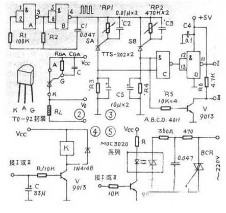
TTS-202 is T0-92 package, its pin arrangement and typical application circuit are shown as in Fig. 2. In the figure, RGA is a resistor that adjusts the threshold temperature. If a potentiometer is used, its threshold temperature is continuously adjustable; CGA is a capacitor for preventing interference, and RL is a load resistor. When the temperature is lower than the threshold temperature, Xing-202 is cut off, and Va is output low; When the temperature reaches or exceeds the threshold temperature, TTS_202 turns on and Vo outputs a high level.
TTS-202 threshold temperature range of 10 ~ 100 ° C, can be adjusted by RGA 470kΩ potentiometer, the greater the resistance value, the lower the threshold temperature. Since TTS_202 has a certain dispersion in production, under the same RGA, its enthalpy temperature has a certain difference, so it should be properly adjusted when applied.
1.2 Circuit working principle
The upper and lower limit temperature control circuit is shown in Figure 3. It consists of a multi-vibrator consisting of 1/24011 (A and B) and RC, an upper and lower threshold temperature controller consisting of two TTS_202s, and an output circuit consisting of the other half 4011 (C and D) and V.
An oscillator composed of 1/24011 A and B outputs a square wave as a power source for two TTS_202s. The purpose is to turn off the temperature switch after it has reached the threshold temperature.
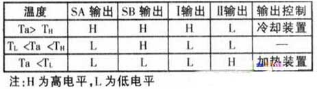
The SA temperature switch is the upper limit temperature switch and SB is the lower limit temperature switch, and the threshold temperature is set (adjusted) by RP1 and RP2, respectively. I and II are two output terminals, and output high level or low level to control the heating or cooling device. Let TH be the upper limit temperature, TL be the lower limit temperature, and Ta be the measured temperature. At different temperatures, the output levels of SA and SB and the output level of I and II are shown in the table below.
The output of I and II can be directly interfaced with the I/O port of the single-chip microcomputer with a working voltage of 5v, and the output of the single chip is used to control the heating or cooling device.
The outputs of I and II can also be controlled by relays or optocouplers, as shown in Figures 4 and 5. In FIG. 4, when the I output is high, a high level (about 5 V) charges the capacitor c. When a certain voltage is reached, the transistor V is turned on, the relay is pulled in, and the contacts can control the refrigerator or the cold water cooling electromagnetic valve. The purpose of the capacitor C in the circuit is to prevent the relay from being frequently turned on and off when the temperature changes around the threshold.
When the circuit of Fig. 4 is connected to the output of II, when the output of II is high, the relay is pulled in, and the normally open contact is used to control the steam to heat the electromagnetic valve or to open the contactor, and the mains is heated by the heater.
In Figure 5, when I outputs a high level, V is turned on, the LED in the photocoupler MOC3020 is lit, so that the internal light control thyristor is triggered to conduct, and the successive external thyristor BCR is turned on, the load R; Get electricity. In the figure, R is a current limiting resistor whose resistance is related to VCC and can be estimated by:
R(kΩ)=(Vcc-1.2V)/10mA When connected to the II output, the 10kΩ resistor in Figure 5 can be appropriately adjusted according to the amplification factor of V if necessary.
1.3 Adjustment method
In actual use, two TTS-202s, SA and SB, should be made into temperature probes. The A, K, and G poles of the TTS-202 are welded with a suitable length of flexible wire, and the welded portions are insulated from each other, and the outside is sealed with an epoxy resin. Prevents malfunctions caused by poor insulation between the electrodes in the liquid. It is better to cover and ground the three flexible conductors with external shielding sleeves.
Place the probe made of SA and SB in the controlled container, and place a thermometer with a precision of 0.1 °C next to the probe to detect the temperature. When the temperature reaches TL, adjust RP2 of SB to make the SB output change from low level to high level; when the temperature reaches TH, adjust the RPI of SA so that the SA output changes from low level to high level. This can be adjusted twice in a row.
First, the upper and lower limits of the temperature control circuit diagram
In industrial production processes, it is often necessary to control the temperature within a certain range.
If the upper limit temperature is TH and the lower limit temperature is TL, the temperature is controlled between TH and TL, as shown in Fig. 1. If the temperature exceeds TH, cooling is required to cool down; if the temperature is lower than TL, the heating is required to be measured.
TTS-202 is a temperature switch which can continuously adjust the control temperature (threshold temperature), and it is also a special one-way thyristor. Unlike a general unidirectional thyristor, it is turned on without triggering current and is temperature controlled:
When the temperature is lower than the threshold temperature, the temperature switch is turned off;
When the threshold temperature is reached or exceeded, the temperature switch is turned on.
The same as a general unidirectional thyristor, once turned on, even if the temperature drops below the threshold temperature, it does not turn off, and only turns off when the on current drops below the holding current.
TTS-202 is T0-92 package, its pin arrangement and typical application circuit are shown as in Fig. 2. In the figure, RGA is a resistor that adjusts the threshold temperature. If a potentiometer is used, its threshold temperature is continuously adjustable; CGA is a capacitor for preventing interference, and RL is a load resistor. When the temperature is lower than the threshold temperature, Xing-202 is cut off, and Va is output low; When the temperature reaches or exceeds the threshold temperature, TTS_202 turns on and Vo outputs a high level.
TTS-202 threshold temperature range of 10 ~ 100 ° C, can be adjusted by RGA 470kΩ potentiometer, the greater the resistance value, the lower the threshold temperature. Since TTS_202 has a certain dispersion in production, under the same RGA, its enthalpy temperature has a certain difference, so it should be properly adjusted when applied.
1.2 Circuit working principle
The upper and lower limit temperature control circuit is shown in Figure 3. It consists of a multi-vibrator consisting of 1/24011 (A and B) and RC, an upper and lower threshold temperature controller consisting of two TTS_202s, and an output circuit consisting of the other half 4011 (C and D) and V.
An oscillator composed of 1/24011 A and B outputs a square wave as a power source for two TTS_202s. The purpose is to turn off the temperature switch after it has reached the threshold temperature.
The SA temperature switch is the upper limit temperature switch and SB is the lower limit temperature switch, and the threshold temperature is set (adjusted) by RP1 and RP2, respectively. I and II are two output terminals, and output high level or low level to control the heating or cooling device. Let TH be the upper limit temperature, TL be the lower limit temperature, and Ta be the measured temperature. At different temperatures, the output levels of SA and SB and the output level of I and II are shown in the table below.
The output of I and II can be directly interfaced with the I/O port of the single-chip microcomputer with a working voltage of 5v, and the output of the single chip is used to control the heating or cooling device.
The outputs of I and II can also be controlled by relays or optocouplers, as shown in Figures 4 and 5. In FIG. 4, when the I output is high, a high level (about 5 V) charges the capacitor c. When a certain voltage is reached, the transistor V is turned on, the relay is pulled in, and the contacts can control the refrigerator or the cold water cooling electromagnetic valve. The purpose of the capacitor C in the circuit is to prevent the relay from being frequently turned on and off when the temperature changes around the threshold.
When the circuit of Fig. 4 is connected to the output of II, when the output of II is high, the relay is pulled in, and the normally open contact is used to control the steam to heat the electromagnetic valve or to open the contactor, and the mains is heated by the heater.
In Figure 5, when I outputs a high level, V is turned on, the LED in the photocoupler MOC3020 is lit, so that the internal light control thyristor is triggered to conduct, and the successive external thyristor BCR is turned on, the load R; Get electricity. In the figure, R is a current limiting resistor whose resistance is related to VCC and can be estimated by:
R(kΩ)=(Vcc-1.2V)/10mA When connected to the II output, the 10kΩ resistor in Figure 5 can be appropriately adjusted according to the amplification factor of V if necessary.
1.3 Adjustment method
In actual use, two TTS-202s, SA and SB, should be made into temperature probes. The A, K, and G poles of the TTS-202 are welded with a suitable length of flexible wire, and the welded portions are insulated from each other, and the outside is sealed with an epoxy resin. Prevents malfunctions caused by poor insulation between the electrodes in the liquid. It is better to cover and ground the three flexible conductors with external shielding sleeves.
Place the probe made of SA and SB in the controlled container, and place a thermometer with a precision of 0.1 °C next to the probe to detect the temperature. When the temperature reaches TL, adjust RP2 of SB to make the SB output change from low level to high level; when the temperature reaches TH, adjust the RPI of SA so that the SA output changes from low level to high level. This can be adjusted twice in a row.


