Sign of Power Supply and Temperature Detection/Display Circuit Diagram of lm358 Electronic Temperature Controller
Circuit working principle
The temperature controller circuit is composed of a power supply circuit, a temperature detecting/display circuit, a reference voltage circuit, and a control circuit, as shown in the figure.
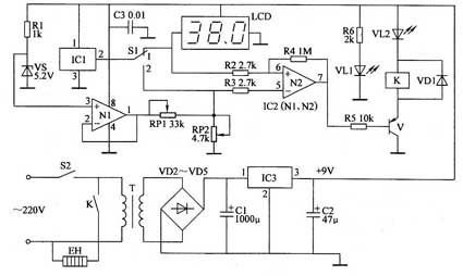
The power circuit is composed of a power switch S2, a power transformer T, rectifier diodes VD2 to VD5, filter capacitors C1, C2, a three-terminal voltage regulator integrated circuit IC3, a resistor R6, and a power indicating LED VL1.
The temperature detecting/display circuit is composed of a temperature sensor integrated circuit IC1, a control switch S1 and an LCD liquid crystal display.
The reference voltage circuit is composed of a resistor RI, a capacitor C3, a Zener diode VS, and N1 inside the operational amplifier integrated circuit IC2 (N1, N2).
The control circuit is composed of potentiometers RP1, RP2, resistors R2 to R5, an amplifier N2 inside IC2, a transistor V, a relay K, a diode VD1, and a light-emitting diode VL2.
After switching on the power supply switch S2, 220V AC voltage is supplied with + 9V working voltage for temperature detection/display circuit and control circuit after T-step-down, VD2-VD5 rectification, C1 filter and IC3 voltage stabilization, and VL1 is lighted by R6.
When S1 is set to the "1" position, it is set to the temperature. The control temperature can be set by adjusting RP1 and RP2 (adjust RP1 first, so that the output voltage of RP2 varies between 0 and 1V, and the corresponding control temperature is 0 to 100 °C). When S1 is placed in the "2" position, it is the temperature display state, and the temperature detected by IC1 is displayed on the LCD liquid crystal display.
When the ambient temperature detected by IC1 is lower than the set temperature of RP2, the output terminal of operational amplifier N2 is at a low level, V saturation is turned on, and K is energized. Its normally open contact is turned on, the heater EH is energized to start heating, and VL2 is lit. When the temperature rises above the set temperature, the operational amplifier N2 outputs a high level, so that V is turned off, K is released, VL2 is extinguished, and EH is turned off to stop heating.
The above work process is carried out repeatedly, so that the temperature of the controlled place is constant near the set temperature.
Component selection
RI ~ R6 use l / 4W metal film resistor or carbon film resistor.
RP1 and RP2 use synthetic membrane potentiometer or multi-turn potentiometer.
Both C1 and C2 use aluminum electrolytic capacitors with a withstand voltage of 16V; C3 uses monolithic capacitors or polyester capacitors.
VD1 ~ VD5 select 1N4007 type silicon rectifier diode.
VS selects 1/2W, 5.2V silicon Zener diode.
Both VL1 and VL2 use high-brightness LEDs with ∮3mm.
V selects 58550 or 3CG8550 silicon PNP transistor.
IC1 selects LM35D type temperature sensor integrated circuit;
IC2 selects LM358 type dual operational amplifier integrated circuit;
IC3 selects 78L09 type three-terminal regulator integrated circuit.
K selects JRX-13F type 9V DC relay. If it is used to control an electric heater above 1 kW, the AC contactor should be added, the AC contactor coil should be controlled by the normally open contact of K, and the heater EH should be controlled by the normally open contact of the AC contactor.
T selects a power transformer with 2 to 5W and a secondary voltage of 12 to 13V.
The LCD liquid crystal display uses a 3-bit half 0~2V liquid crystal head.
S1 selects single-pole two-position switch: S2 selects 10A, 220Y power switch.
The temperature controller circuit is composed of a power supply circuit, a temperature detecting/display circuit, a reference voltage circuit, and a control circuit, as shown in the figure.
The power circuit is composed of a power switch S2, a power transformer T, rectifier diodes VD2 to VD5, filter capacitors C1, C2, a three-terminal voltage regulator integrated circuit IC3, a resistor R6, and a power indicating LED VL1.
The temperature detecting/display circuit is composed of a temperature sensor integrated circuit IC1, a control switch S1 and an LCD liquid crystal display.
The reference voltage circuit is composed of a resistor RI, a capacitor C3, a Zener diode VS, and N1 inside the operational amplifier integrated circuit IC2 (N1, N2).
The control circuit is composed of potentiometers RP1, RP2, resistors R2 to R5, an amplifier N2 inside IC2, a transistor V, a relay K, a diode VD1, and a light-emitting diode VL2.
After switching on the power supply switch S2, 220V AC voltage is supplied with + 9V working voltage for temperature detection/display circuit and control circuit after T-step-down, VD2-VD5 rectification, C1 filter and IC3 voltage stabilization, and VL1 is lighted by R6.
When S1 is set to the "1" position, it is set to the temperature. The control temperature can be set by adjusting RP1 and RP2 (adjust RP1 first, so that the output voltage of RP2 varies between 0 and 1V, and the corresponding control temperature is 0 to 100 °C). When S1 is placed in the "2" position, it is the temperature display state, and the temperature detected by IC1 is displayed on the LCD liquid crystal display.
When the ambient temperature detected by IC1 is lower than the set temperature of RP2, the output terminal of operational amplifier N2 is at a low level, V saturation is turned on, and K is energized. Its normally open contact is turned on, the heater EH is energized to start heating, and VL2 is lit. When the temperature rises above the set temperature, the operational amplifier N2 outputs a high level, so that V is turned off, K is released, VL2 is extinguished, and EH is turned off to stop heating.
The above work process is carried out repeatedly, so that the temperature of the controlled place is constant near the set temperature.
Component selection
RI ~ R6 use l / 4W metal film resistor or carbon film resistor.
RP1 and RP2 use synthetic membrane potentiometer or multi-turn potentiometer.
Both C1 and C2 use aluminum electrolytic capacitors with a withstand voltage of 16V; C3 uses monolithic capacitors or polyester capacitors.
VD1 ~ VD5 select 1N4007 type silicon rectifier diode.
VS selects 1/2W, 5.2V silicon Zener diode.
Both VL1 and VL2 use high-brightness LEDs with ∮3mm.
V selects 58550 or 3CG8550 silicon PNP transistor.
IC1 selects LM35D type temperature sensor integrated circuit;
IC2 selects LM358 type dual operational amplifier integrated circuit;
IC3 selects 78L09 type three-terminal regulator integrated circuit.
K selects JRX-13F type 9V DC relay. If it is used to control an electric heater above 1 kW, the AC contactor should be added, the AC contactor coil should be controlled by the normally open contact of K, and the heater EH should be controlled by the normally open contact of the AC contactor.
T selects a power transformer with 2 to 5W and a secondary voltage of 12 to 13V.
The LCD liquid crystal display uses a 3-bit half 0~2V liquid crystal head.
S1 selects single-pole two-position switch: S2 selects 10A, 220Y power switch.


