New thermostats simultaneously master the functions of lifting and lowering control
Damage to the refrigeration system is one of the main reasons for the scrapping of the refrigerator, but the cabinet is intact, and many laboratories require a constant temperature incubator. It is of great practical significance to transform a waste refrigerator into a constant temperature incubator. The author is in the practice of transforming scrap refrigerators into constant temperature incubators (hereinafter referred to as constant temperature incubators). Using the single-chip circuit, the temperature control accuracy is improved by optimizing the programming, so that the technical performance index meets or exceeds the requirements of the current constant temperature incubator on the market.
The main technical indicators are as follows:
Temperature control range: 5-40 ° C;
Temperature fluctuation tolerance: ± 0.2 ° C; temperature uniformity tolerance; ± 0.5 ° C.
When renovating the scrap refrigerator into a constant temperature incubator, first remove the refrigeration system of the refrigerator. When removing it, pay attention to protect the cabinet, and then install the thermostat and fan in the proper position. The thermostat incubator needs both heating and cooling, while the commercial thermostat only has the single function of heating or cooling, which can not meet the requirements of the thermostat incubator. Therefore, the key to the renovation of scrap refrigerators is to develop a kind of temperature controller which integrates the functions of raising and lowering temperature and has high precision of temperature control. This article describes a self-made constant temperature incubator temperature controller (referred to as temperature controller).
1, the working principle
The thermostat uses the 8031 single-chip microcomputer as the core, and uses the electric contact mercury thermometer for temperature setting. The temperature control of the constant temperature incubator is realized by regulating the on-off and off-cycle of the electric contact mercury thermometer. The single-chip microcomputer automatically detects the heating or cooling by detecting the on-off state of the electric contact mercury thermometer. When the temperature needs to be raised, the heating plate heating, the single-chip control and the two-way thyristor power adjustment mode are adopted. When it is necessary to cool down, the semiconductor refrigerator is cooled and the single-chip control mode is adopted to make the temperature control precision reach a high level.
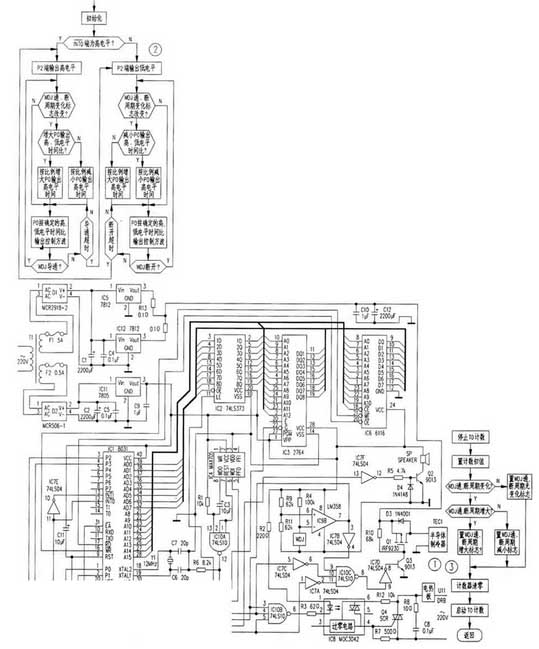
The circuit is shown in Figure 1. It is mainly composed of automatic identification circuit for raising and lowering, heating control circuit, cooling control circuit and temperature abnormal alarm circuit.
 1. Automatic recognition circuit for raising and lowering temperature
When the temperature rise is required, the electrical contact mercury thermometer is in the off state (WDJ is not conducting). Operational amplifier LM358 (IC9B) has a high level⑤foot. Its⑥foot is 2.5V obtained by dividing the voltage between R9 and RI1. The⑦foot outputs a high level to the⑫foot of single chip IC 1.When the need to cool down, according to the above analysis, the microcontroller IC ⑫ pin 1 is low. After the initialization of MCU, first read the data from foot ⑫. If foot⑫is input as "1", it indicates that the thermostat needs to be heated, otherwise it needs to be cooled. When the temperature rises, the single chip computer makes the output of the P2 port flat. When cooling down, the MCU makes the P2 port output low level.
2. Temperature control circuit
When the temperature needs to be raised, the 7th pin of IC9B outputs a high level, so that the 3 pin of the NAND gate IC10B (74LS10) is high. At the same time, the high level of the 7-pin output of IC9B passes through the non-gate IC7B to make the 9-pin of the NAND gate IC10C low, and the NAND gate IC10C is turned off, and the cooling circuit cannot work. When the MCU automatically recognizes that the oven needs to heat up, set the P2 terminal (output high level) and output a square wave with a duty ratio of 1:1 from the PO terminal. IC l OB 5 feet are high level, 4 feet are square wave, its 6-pin output and 5-pin inverted square wave, IC8 is energized, the two-way thyristor SCR is turned on, the hot plate starts to supply to the incubator heat. At this time, although the 9th pin of IC10C becomes a high level, the 11th pin is at a low level, so the NAND gate IC10C is kept off, and the temperature drop circuit still does not work.
When the temperature of the incubator reaches the set temperature, WDJ turns on. At this time, IC9B's 5-pin potential is lower than 6-pin, 7-pin output is low, NAND gate IC10B is turned off, its 6-pin output is high, IC8 stops working, and the hot plate stops heating. At the same time, IC9B's 7-pin output is sent low to IC1's INTO C7, its falling edge causes IC 1 interrupt, and the external interrupt service routine causes IC 1's internal timer to start counting.
After the heating plate stops heating, the temperature of the incubator begins to drop. After a period of time, the WDJ is disconnected, and the electric heating plate starts heating the temperature control device again. When heated to the set temperature, WDJ is turned on, and the 7th pin of IC9 outputs a low level, on the one hand, the heating plate stops heating; On the other hand, the INTO interrupt is triggered, so that the TO stops counting, after analyzing and judging the on and off periods of the WDJ and juxtaposing the corresponding flag bits. The TO starts counting again, and stores the on and off cycles of the current WDJ for comparison with the next on and off cycles. TO works in mode 2, when the low-order timing unit overflows, the TO interrupt will be triggered to complete the carry from the low-order timing unit to the high-order timing unit, that is, TO constitutes a spreadsheet timer. The main program performs calculation processing according to the flag bit, and increases or decreases the duty ratio of the square wave output square wave at a certain ratio in the basic period (WDJ once-on, off period), and outputs the temperature control pulse according to the time ratio. In this way, the number of conduction cycles of the triac SCR is changed within a certain period of time, and the power of the hot plate is controlled. The control algorithm is as follows:
If the current on/off period of the WDJ is less than the last time, the ratio of the high and low time of the PO output is reduced in the basic period. Otherwise, the PO output high and low time ratios are increased in the basic period, and finally the WDJ's on and off periods are the shortest. The PO end outputs the temperature control pulse according to the duty cycle pulse determined thereby, and the heat lost by the oven and the heat provided by the electric heating plate substantially reach a dynamic balance, so that the control precision reaches a high level. It can be seen that the hot plate is not only controlled by the WDJ, but also controlled by the PO output pulse. The WDJ controls whether the temperature control device is heated, and the pulse of the PO output controls the time ratio of the two-way thyristor on and off, thereby controlling the power of the hot plate.
3. Cooling control circuit
When the need to cool down, IC9B gate output pin 7 exhibits a low level. After the inversion of the non-gate IC7B, on the one hand, the 9-pin of the NAND gate IC10C (74LS10) is at a high level, on the one hand, the IC10B is turned off, and the temperature-increasing circuit does not operate. When the single-chip recognizes that the oven needs to be cooled, the P2 terminal is reset (output low level), and the P0 terminal outputs a square wave with a duty ratio of 1:1. The low level of the P2 output is inverted by IC7A and sent to the 11th pin of IC10C, so that the 8-pin output of IC10C is released. Transistor 9013, high-power FET Q1 continues to work with the wave, the semiconductor cooler works, and the oven begins to cool down.
When the temperature drops to the set value, the WDJ is turned off and the cooling circuit stops working. Since the incubator is still in the cooling state at this time, the P2 terminal of the single chip is at a low level, the NAND gate IC10B is turned off, and the hot plate does not work. After the semiconductor refrigerator stops cooling, the temperature begins to rise. After a period of time, the WDJ turns on, and the semiconductor cooler starts to cool down again. The cooling process is similar to the temperature rise and temperature control process. The difference is that the temperature-controlled temperature control circuit uses the adjusted square wave output of the single-chip PO terminal to control the working time of the semiconductor refrigerator. Finally, the heat absorbed by the incubator from the outside and the heat absorbed by the semiconductor cooler from the tank are basically balanced, so that the control precision reaches a high level.
4. Temperature abnormal alarm circuit
When the temperature control circuit is working normally, the on/off cycle of the electrical contact mercury thermometer is generally several tens of seconds. If the rise and fall control circuit fails, this cycle will inevitably be abnormal. The upper limit of the cycle is set according to the volume of the oven (set in the timing program). When the period exceeds the upper limit value, the P3 terminal of the single-chip microcomputer outputs a low level, and after the IC7F is inverted, the Q2 is satisfactorily turned on, and the self-contained micro-dc sounder SP is energized to generate an alarm sound.
Second, software design
The control software consists of three parts: the main program, the external interrupt INTO service program, and the timer TO interrupt service program.
Third, reliability design
The temperature controller uses semiconductor devices such as a thyristor and a field effect transistor for controlling the rising and lowering elements of the electric heating plate and the semiconductor refrigerator, thereby eliminating the disadvantage that the relay contact is liable to cause a temperature loss due to poor oxidation contact.
This application also uses the microprocessor monitoring circuit produced by MAX. When the program runs away, the WDI end will be "less than the pulse signal in 1.6s, and the WDO end will output a low level, so that the 10th pin of IC10A outputs a high level, and IC 1 is reset. Effectively prevent the program from running away and causing temperature to run out of control. In addition, software traps are added at appropriate locations in the unused population and in the white space of the program memory to prevent the program from running away.
Automatic correction of misjudgment of rising and cooling. When the MCU is in a warming state and has just reached the predetermined temperature and stops, if it is in the event of a power outage, it will suddenly call. The MCU will restart and misjudge the incubator should be in the cooling state. When the MCU is in the cooling state, there is a similar situation. The method of automatically correcting this misjudgment by the single-chip microcomputer is that after the reset of the single-chip microcomputer, the device for raising and lowering temperature is automatically controlled according to the detected rising and falling state. If the number of minutes (according to the volume of the box is set by software), the state of the internal contact mercury thermometer does not change, indicating that the discrimination is wrong, the microcontroller then changes the level of the P2 terminal, thereby changing the state of the rise and fall.
The main technical indicators are as follows:
Temperature control range: 5-40 ° C;
Temperature fluctuation tolerance: ± 0.2 ° C; temperature uniformity tolerance; ± 0.5 ° C.
When renovating the scrap refrigerator into a constant temperature incubator, first remove the refrigeration system of the refrigerator. When removing it, pay attention to protect the cabinet, and then install the thermostat and fan in the proper position. The thermostat incubator needs both heating and cooling, while the commercial thermostat only has the single function of heating or cooling, which can not meet the requirements of the thermostat incubator. Therefore, the key to the renovation of scrap refrigerators is to develop a kind of temperature controller which integrates the functions of raising and lowering temperature and has high precision of temperature control. This article describes a self-made constant temperature incubator temperature controller (referred to as temperature controller).
1, the working principle
The thermostat uses the 8031 single-chip microcomputer as the core, and uses the electric contact mercury thermometer for temperature setting. The temperature control of the constant temperature incubator is realized by regulating the on-off and off-cycle of the electric contact mercury thermometer. The single-chip microcomputer automatically detects the heating or cooling by detecting the on-off state of the electric contact mercury thermometer. When the temperature needs to be raised, the heating plate heating, the single-chip control and the two-way thyristor power adjustment mode are adopted. When it is necessary to cool down, the semiconductor refrigerator is cooled and the single-chip control mode is adopted to make the temperature control precision reach a high level.
The circuit is shown in Figure 1. It is mainly composed of automatic identification circuit for raising and lowering, heating control circuit, cooling control circuit and temperature abnormal alarm circuit.
When the temperature rise is required, the electrical contact mercury thermometer is in the off state (WDJ is not conducting). Operational amplifier LM358 (IC9B) has a high level⑤foot. Its⑥foot is 2.5V obtained by dividing the voltage between R9 and RI1. The⑦foot outputs a high level to the⑫foot of single chip IC 1.When the need to cool down, according to the above analysis, the microcontroller IC ⑫ pin 1 is low. After the initialization of MCU, first read the data from foot ⑫. If foot⑫is input as "1", it indicates that the thermostat needs to be heated, otherwise it needs to be cooled. When the temperature rises, the single chip computer makes the output of the P2 port flat. When cooling down, the MCU makes the P2 port output low level.
2. Temperature control circuit
When the temperature needs to be raised, the 7th pin of IC9B outputs a high level, so that the 3 pin of the NAND gate IC10B (74LS10) is high. At the same time, the high level of the 7-pin output of IC9B passes through the non-gate IC7B to make the 9-pin of the NAND gate IC10C low, and the NAND gate IC10C is turned off, and the cooling circuit cannot work. When the MCU automatically recognizes that the oven needs to heat up, set the P2 terminal (output high level) and output a square wave with a duty ratio of 1:1 from the PO terminal. IC l OB 5 feet are high level, 4 feet are square wave, its 6-pin output and 5-pin inverted square wave, IC8 is energized, the two-way thyristor SCR is turned on, the hot plate starts to supply to the incubator heat. At this time, although the 9th pin of IC10C becomes a high level, the 11th pin is at a low level, so the NAND gate IC10C is kept off, and the temperature drop circuit still does not work.
When the temperature of the incubator reaches the set temperature, WDJ turns on. At this time, IC9B's 5-pin potential is lower than 6-pin, 7-pin output is low, NAND gate IC10B is turned off, its 6-pin output is high, IC8 stops working, and the hot plate stops heating. At the same time, IC9B's 7-pin output is sent low to IC1's INTO C7, its falling edge causes IC 1 interrupt, and the external interrupt service routine causes IC 1's internal timer to start counting.
After the heating plate stops heating, the temperature of the incubator begins to drop. After a period of time, the WDJ is disconnected, and the electric heating plate starts heating the temperature control device again. When heated to the set temperature, WDJ is turned on, and the 7th pin of IC9 outputs a low level, on the one hand, the heating plate stops heating; On the other hand, the INTO interrupt is triggered, so that the TO stops counting, after analyzing and judging the on and off periods of the WDJ and juxtaposing the corresponding flag bits. The TO starts counting again, and stores the on and off cycles of the current WDJ for comparison with the next on and off cycles. TO works in mode 2, when the low-order timing unit overflows, the TO interrupt will be triggered to complete the carry from the low-order timing unit to the high-order timing unit, that is, TO constitutes a spreadsheet timer. The main program performs calculation processing according to the flag bit, and increases or decreases the duty ratio of the square wave output square wave at a certain ratio in the basic period (WDJ once-on, off period), and outputs the temperature control pulse according to the time ratio. In this way, the number of conduction cycles of the triac SCR is changed within a certain period of time, and the power of the hot plate is controlled. The control algorithm is as follows:
If the current on/off period of the WDJ is less than the last time, the ratio of the high and low time of the PO output is reduced in the basic period. Otherwise, the PO output high and low time ratios are increased in the basic period, and finally the WDJ's on and off periods are the shortest. The PO end outputs the temperature control pulse according to the duty cycle pulse determined thereby, and the heat lost by the oven and the heat provided by the electric heating plate substantially reach a dynamic balance, so that the control precision reaches a high level. It can be seen that the hot plate is not only controlled by the WDJ, but also controlled by the PO output pulse. The WDJ controls whether the temperature control device is heated, and the pulse of the PO output controls the time ratio of the two-way thyristor on and off, thereby controlling the power of the hot plate.
3. Cooling control circuit
When the need to cool down, IC9B gate output pin 7 exhibits a low level. After the inversion of the non-gate IC7B, on the one hand, the 9-pin of the NAND gate IC10C (74LS10) is at a high level, on the one hand, the IC10B is turned off, and the temperature-increasing circuit does not operate. When the single-chip recognizes that the oven needs to be cooled, the P2 terminal is reset (output low level), and the P0 terminal outputs a square wave with a duty ratio of 1:1. The low level of the P2 output is inverted by IC7A and sent to the 11th pin of IC10C, so that the 8-pin output of IC10C is released. Transistor 9013, high-power FET Q1 continues to work with the wave, the semiconductor cooler works, and the oven begins to cool down.
When the temperature drops to the set value, the WDJ is turned off and the cooling circuit stops working. Since the incubator is still in the cooling state at this time, the P2 terminal of the single chip is at a low level, the NAND gate IC10B is turned off, and the hot plate does not work. After the semiconductor refrigerator stops cooling, the temperature begins to rise. After a period of time, the WDJ turns on, and the semiconductor cooler starts to cool down again. The cooling process is similar to the temperature rise and temperature control process. The difference is that the temperature-controlled temperature control circuit uses the adjusted square wave output of the single-chip PO terminal to control the working time of the semiconductor refrigerator. Finally, the heat absorbed by the incubator from the outside and the heat absorbed by the semiconductor cooler from the tank are basically balanced, so that the control precision reaches a high level.
4. Temperature abnormal alarm circuit
When the temperature control circuit is working normally, the on/off cycle of the electrical contact mercury thermometer is generally several tens of seconds. If the rise and fall control circuit fails, this cycle will inevitably be abnormal. The upper limit of the cycle is set according to the volume of the oven (set in the timing program). When the period exceeds the upper limit value, the P3 terminal of the single-chip microcomputer outputs a low level, and after the IC7F is inverted, the Q2 is satisfactorily turned on, and the self-contained micro-dc sounder SP is energized to generate an alarm sound.
Second, software design
The control software consists of three parts: the main program, the external interrupt INTO service program, and the timer TO interrupt service program.
Third, reliability design
The temperature controller uses semiconductor devices such as a thyristor and a field effect transistor for controlling the rising and lowering elements of the electric heating plate and the semiconductor refrigerator, thereby eliminating the disadvantage that the relay contact is liable to cause a temperature loss due to poor oxidation contact.
This application also uses the microprocessor monitoring circuit produced by MAX. When the program runs away, the WDI end will be "less than the pulse signal in 1.6s, and the WDO end will output a low level, so that the 10th pin of IC10A outputs a high level, and IC 1 is reset. Effectively prevent the program from running away and causing temperature to run out of control. In addition, software traps are added at appropriate locations in the unused population and in the white space of the program memory to prevent the program from running away.
Automatic correction of misjudgment of rising and cooling. When the MCU is in a warming state and has just reached the predetermined temperature and stops, if it is in the event of a power outage, it will suddenly call. The MCU will restart and misjudge the incubator should be in the cooling state. When the MCU is in the cooling state, there is a similar situation. The method of automatically correcting this misjudgment by the single-chip microcomputer is that after the reset of the single-chip microcomputer, the device for raising and lowering temperature is automatically controlled according to the detected rising and falling state. If the number of minutes (according to the volume of the box is set by software), the state of the internal contact mercury thermometer does not change, indicating that the discrimination is wrong, the microcontroller then changes the level of the P2 terminal, thereby changing the state of the rise and fall.


