Digital display thermostat circuit diagram design uses 8-bit single-chip AT89C52 as the main control chip
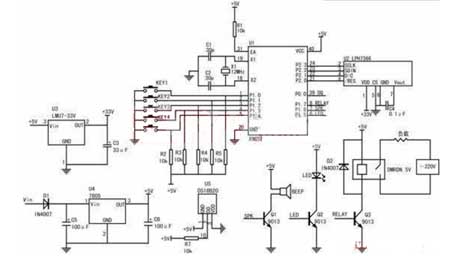
This circuit selects the most commonly used 8-bit single-chip AT89C52 on the market as the main control chip, as shown in Figure 1. Through the P2.0, P2.1, P2.2, P2.3 port software simulation SPI port and the LCD module's main control chip LPH7366 serial communication. Single bus communication with the DS18B20 via P0.0. P1.5, P1.6, and P1.7 are output control ports that control piezoelectric ceramic sheets, LED light-emitting diodes, and relays, respectively.
The basic idea of the design of this numerical thermometer:
The DS18B20 is used as a temperature sensing element, and the ambient temperature data is converted into a digital signal and sent to the AT89C52. The AT89C52 sends the converted temperature value to the LCD display through the internal calculation of the program. This design can display data such as temperature and time in real time on the LCD. By displaying real-time information such as the current ambient temperature and time, the user can easily control the load through these information.


