Design Principle of Switching Circuit for Electric Blanket Temperature Controller
Temperature control of electric blanket
Electric blanket, also known as electric raft, is a contact type electric heating appliance. It has a special soft-corrugated electric heating element with a standard insulation performance woven or sewn into the felt, and emits heat when it is energized. It is mainly used for people to improve the temperature in the bed to achieve heating. It can also be used for dehumidification of bedding. It has a low power consumption, adjustable temperature, easy to use and wide use, and has a history of more than 100 years.
Two types of structure of electric blanket
1, without signal line type: Used in ordinary electric blankets. The electrothermal alloy wire used has a linear shape, but is more spirally wound around the heat-resistant core wire and coated with a layer of heat-resistant resin.
2, with signal line type: Used in thermostat type electric blankets. The core is made of glass fiber or polyester yarn wrapped with a flexible and flexible electric heating wire (or foil tape). The outside is covered with a layer of nylon heat sensitive layer or special plastic heat sensitive layer, and then a copper alloy signal wire is wound around the heat sensitive layer, and the outermost layer is coated with a heat resistant resin. When the temperature at any point on the electric blanket exceeds the predetermined value, the sensible layer on the corresponding electric heating wire at this place changes from insulator to good conductor, which makes the control circuit connected and the electric blanket cut off, so as to achieve the purpose of temperature control and safety protection.
For ordinary electric blankets without signal line type electric heating elements, if temperature control is to be realized, there are generally two types of temperature control elements: One type is a superheated safety thermostat. The electric blanket of each bed needs about 8-9, which is connected in series on the electric heating element to play a safety protection role; The other type is a thermostat controller that is placed at the head or hand to adjust the temperature. An electric blanket using an electric heating element with a signal line requires only a thermostat controller.
At present, many electric blankets use manual switches for temperature control. It is controlled by a fast hot file and a slow hot file, so that the internal temperature of the electric blanket is difficult to control to work at a constant temperature, which brings a lot of trouble to the user.
How electric blankets work
Used in temperature-adjusting electric blanket. The core is made of glass fiber or polyester yarn, which is wrapped with a flexible and flexible electric heating wire (or foil tape), and is covered with a layer of nylon heat sensitive layer or special plastic heat sensitive layer. A copper alloy signal wire is wound around the heat sensitive layer, and a layer of heat resistant resin is applied to the outermost layer. For ordinary electric blankets without signal line type electric heating elements, if temperature control is to be realized, there are generally two types of temperature control elements: One type is a superheated safety thermostat. The electric blanket of each bed needs about 8-9, which is connected in series on the electric heating element to play a safety protection role; The other type is a thermostat controller that is placed at the head or hand to adjust the temperature. An electric blanket using an electric heating element with a signal line requires only a thermostat controller.
working principle:
The circuit is as shown. The IC in the figure is the NE555 time base circuit. RP3 is a temperature-controlled adjustment potentiometer whose sliding arm potential determines the trigger potential V2 of the IC and the valve potential Vf, and V5=Vf=2Vz. 220V AC voltage via C2. R2 current limiting step-down, D1, D2 rectification, C1 filtering, after DW voltage regulation, obtain a voltage of about 9V for the NE555 time base circuit. RP1 is a temperature-controlled adjustment potentiometer whose sliding arm potential determines NE555 trigger potential V2 and valve potential Vf, and V5-Vf-2Vz. When the power is turned on at room temperature, because when V2 < Vz, V6 < Vf has been adjusted, NE555 turns over, 3 feet turn to low level, BCR cuts off, electric heating wire stops heating, temperature begins to drop gradually, ICEO of BG1 decreases gradually, V2, V6 decreases. When V6 < VF, V2 ≤ VZ, the potential of the 3 pin of the IC returns to a high potential, and the BCR triggers the conduction again, and the heating wire starts to heat up again. Actually, when adjusting RP2 to make V2=12V6, the temperature difference is zero; and V2=“V6 is the largest.
Component selection: BG1 can use PNP type manifolds such as 3AX and 3AG: BCR uses small bidirectional thyristor with 400V or more.
Note: V2, V5, and V6 are the voltages of the 2, 5, and 6 pins of NE555 circuit.
Production points: The thermal sensor BG1 can be taken out with a temperature-resistant thin flexible wire, and it is placed in a capacitor aluminum case together with the pin connector, and a thermal grease is injected to form a temperature probe. When using, put the probe in the appropriate part.
Electric blanket thermostat circuit (2)
1, burned fuse and temperature control insurance damage;
2, rw1, rw2 bad contact;
Processing methods: Replace the fuse, temperature control insurance is not easy to buy, so you can directly replace it with a fuse; Poor contact between the two potentiometers, can be washed with alcohol.
Introduction to circuit principle
The working principle of the circuit is shown in Figure 1. It mainly consists of power failure self-locking circuit, over voltage protection circuit and automatic constant temperature control circuit. When the button switch S2 is pressed, the 220V AC power is stepped down by the capacitor C2, the V6 and V7 are regulated and rectified, and the C3 is filtered for the relay J to be used. At this time, the J is energized and the normally open contact J1 is turned on, so that the circuit is self-locking. At this time, even if the push button switch S2 is released, power supply to the electric blanket and the relay J can be maintained. When the electric blanket encounters power failure in the process of use, the relay J is powered off, and the normally open electric shock J1 is disconnected, so the electric blanket does not work. When the power grid is restored, the relay and the electric blanket cannot be automatically connected to the power supply. Only the s2 can be pressed again, the relay J is sucked, and the electric blanket will be re-energized.
Rt is a positive temperature coefficient thermistor whose internal resistance varies with the temperature sensed, that is, the internal resistance increases when the temperature is high, and vice versa. The electric heating blanket constant temperature control circuit is composed of the rectifying diodes V2 to V5, the unidirectional thyristor SCR, the bidirectional triggering diode V1, the positive temperature coefficient thermistor Rt, the capacitor C1 and the potentiometer RP.
The control process is: After the AC power is rectified by the V2 to V5 bridge, it becomes DC power, and is charged to C1 through RP and Rt. When the voltage on both ends of C1 reaches a certain value, the bidirectional trigger diode is turned on and turned on and is in a discharging state. At this time, the one-way thyristor is triggered to conduct, so that the electric blanket is energized. When the internal temperature of the electric blanket rises to a certain value, the internal resistance of the thermistor Rt is large. The voltage dropped on C1 is small, and V1 cannot be broken down. Then the SCR is turned off, and the corresponding electric blanket is not powered off. At this time, the electric blanket is in a cooling state. When the temperature of the electric blanket drops to a certain value, the above control process is repeated, so that the temperature of the electric blanket is kept at a constant value. If an overvoltage occurs in the power grid, the varistor MY is internally short-circuited (ie, in an on state), and the fuse RD is quickly blown, thereby providing automatic protection against overvoltage.
Electric blanket, also known as electric raft, is a contact type electric heating appliance. It has a special soft-corrugated electric heating element with a standard insulation performance woven or sewn into the felt, and emits heat when it is energized. It is mainly used for people to improve the temperature in the bed to achieve heating. It can also be used for dehumidification of bedding. It has a low power consumption, adjustable temperature, easy to use and wide use, and has a history of more than 100 years.
Two types of structure of electric blanket
1, without signal line type: Used in ordinary electric blankets. The electrothermal alloy wire used has a linear shape, but is more spirally wound around the heat-resistant core wire and coated with a layer of heat-resistant resin.
2, with signal line type: Used in thermostat type electric blankets. The core is made of glass fiber or polyester yarn wrapped with a flexible and flexible electric heating wire (or foil tape). The outside is covered with a layer of nylon heat sensitive layer or special plastic heat sensitive layer, and then a copper alloy signal wire is wound around the heat sensitive layer, and the outermost layer is coated with a heat resistant resin. When the temperature at any point on the electric blanket exceeds the predetermined value, the sensible layer on the corresponding electric heating wire at this place changes from insulator to good conductor, which makes the control circuit connected and the electric blanket cut off, so as to achieve the purpose of temperature control and safety protection.
For ordinary electric blankets without signal line type electric heating elements, if temperature control is to be realized, there are generally two types of temperature control elements: One type is a superheated safety thermostat. The electric blanket of each bed needs about 8-9, which is connected in series on the electric heating element to play a safety protection role; The other type is a thermostat controller that is placed at the head or hand to adjust the temperature. An electric blanket using an electric heating element with a signal line requires only a thermostat controller.
At present, many electric blankets use manual switches for temperature control. It is controlled by a fast hot file and a slow hot file, so that the internal temperature of the electric blanket is difficult to control to work at a constant temperature, which brings a lot of trouble to the user.
How electric blankets work
Used in temperature-adjusting electric blanket. The core is made of glass fiber or polyester yarn, which is wrapped with a flexible and flexible electric heating wire (or foil tape), and is covered with a layer of nylon heat sensitive layer or special plastic heat sensitive layer. A copper alloy signal wire is wound around the heat sensitive layer, and a layer of heat resistant resin is applied to the outermost layer. For ordinary electric blankets without signal line type electric heating elements, if temperature control is to be realized, there are generally two types of temperature control elements: One type is a superheated safety thermostat. The electric blanket of each bed needs about 8-9, which is connected in series on the electric heating element to play a safety protection role; The other type is a thermostat controller that is placed at the head or hand to adjust the temperature. An electric blanket using an electric heating element with a signal line requires only a thermostat controller.
Electric blanket temperature controller circuit (1)
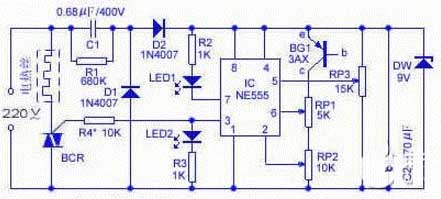
As shown in the figure, it is an electric blanket temperature controller composed of a time base circuit NE555, an AC switch control device BCR, a temperature adjustment potentiometer, a Zener diode, and the like. Generally, electric blankets have two speeds of high temperature and low temperature. This circuit is an electric blanket temperature controller that can control the temperature of the electric blanket to a suitable range.
working principle:
The circuit is as shown. The IC in the figure is the NE555 time base circuit. RP3 is a temperature-controlled adjustment potentiometer whose sliding arm potential determines the trigger potential V2 of the IC and the valve potential Vf, and V5=Vf=2Vz. 220V AC voltage via C2. R2 current limiting step-down, D1, D2 rectification, C1 filtering, after DW voltage regulation, obtain a voltage of about 9V for the NE555 time base circuit. RP1 is a temperature-controlled adjustment potentiometer whose sliding arm potential determines NE555 trigger potential V2 and valve potential Vf, and V5-Vf-2Vz. When the power is turned on at room temperature, because when V2 < Vz, V6 < Vf has been adjusted, NE555 turns over, 3 feet turn to low level, BCR cuts off, electric heating wire stops heating, temperature begins to drop gradually, ICEO of BG1 decreases gradually, V2, V6 decreases. When V6 < VF, V2 ≤ VZ, the potential of the 3 pin of the IC returns to a high potential, and the BCR triggers the conduction again, and the heating wire starts to heat up again. Actually, when adjusting RP2 to make V2=12V6, the temperature difference is zero; and V2=“V6 is the largest.
Component selection: BG1 can use PNP type manifolds such as 3AX and 3AG: BCR uses small bidirectional thyristor with 400V or more.
Note: V2, V5, and V6 are the voltages of the 2, 5, and 6 pins of NE555 circuit.
Production points: The thermal sensor BG1 can be taken out with a temperature-resistant thin flexible wire, and it is placed in a capacitor aluminum case together with the pin connector, and a thermal grease is injected to form a temperature probe. When using, put the probe in the appropriate part.
Electric blanket thermostat circuit (2)
Rainbow brand 1329a electric blanket temperature control circuit diagram
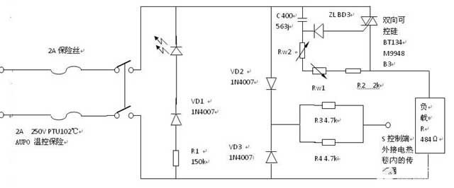
The most common faults:1, burned fuse and temperature control insurance damage;
2, rw1, rw2 bad contact;
Processing methods: Replace the fuse, temperature control insurance is not easy to buy, so you can directly replace it with a fuse; Poor contact between the two potentiometers, can be washed with alcohol.
Electric blanket thermostat circuit (3)
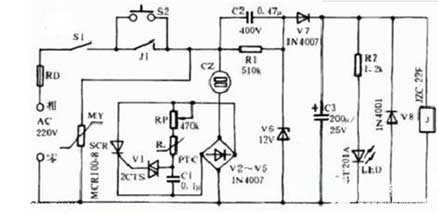
At present, many electric blankets use manual switches for temperature control. It is controlled by a fast hot file and a slow hot file, so that the internal temperature of the electric blanket is difficult to control to work at a constant temperature, which brings a lot of trouble to the user. This article introduces an electric blanket automatic control circuit, which can work at a predetermined temperature, and can also play the role of power-off self-locking and over-voltage protection.Introduction to circuit principle
The working principle of the circuit is shown in Figure 1. It mainly consists of power failure self-locking circuit, over voltage protection circuit and automatic constant temperature control circuit. When the button switch S2 is pressed, the 220V AC power is stepped down by the capacitor C2, the V6 and V7 are regulated and rectified, and the C3 is filtered for the relay J to be used. At this time, the J is energized and the normally open contact J1 is turned on, so that the circuit is self-locking. At this time, even if the push button switch S2 is released, power supply to the electric blanket and the relay J can be maintained. When the electric blanket encounters power failure in the process of use, the relay J is powered off, and the normally open electric shock J1 is disconnected, so the electric blanket does not work. When the power grid is restored, the relay and the electric blanket cannot be automatically connected to the power supply. Only the s2 can be pressed again, the relay J is sucked, and the electric blanket will be re-energized.
Rt is a positive temperature coefficient thermistor whose internal resistance varies with the temperature sensed, that is, the internal resistance increases when the temperature is high, and vice versa. The electric heating blanket constant temperature control circuit is composed of the rectifying diodes V2 to V5, the unidirectional thyristor SCR, the bidirectional triggering diode V1, the positive temperature coefficient thermistor Rt, the capacitor C1 and the potentiometer RP.
The control process is: After the AC power is rectified by the V2 to V5 bridge, it becomes DC power, and is charged to C1 through RP and Rt. When the voltage on both ends of C1 reaches a certain value, the bidirectional trigger diode is turned on and turned on and is in a discharging state. At this time, the one-way thyristor is triggered to conduct, so that the electric blanket is energized. When the internal temperature of the electric blanket rises to a certain value, the internal resistance of the thermistor Rt is large. The voltage dropped on C1 is small, and V1 cannot be broken down. Then the SCR is turned off, and the corresponding electric blanket is not powered off. At this time, the electric blanket is in a cooling state. When the temperature of the electric blanket drops to a certain value, the above control process is repeated, so that the temperature of the electric blanket is kept at a constant value. If an overvoltage occurs in the power grid, the varistor MY is internally short-circuited (ie, in an on state), and the fuse RD is quickly blown, thereby providing automatic protection against overvoltage.


