Control principle and manufacturing method of simple temperature controller using 555 time base circuit
This circuit is a temperature automatic controller consisting of a 555 time base integrated circuit and few peripheral components. Because the voltages at various points in the circuit are from the same DC power supply, there is no need for a regulated power supply with good performance, and the capacitor step-down method can work reliably. Circuit components are low in price, small in size, and easy to make in amateur conditions. The temperature automatic controller made by this circuit can be used for industrial heating and electric heating control of households with good effect.
First, the circuit principle of the circuit
As shown in Figure 1.
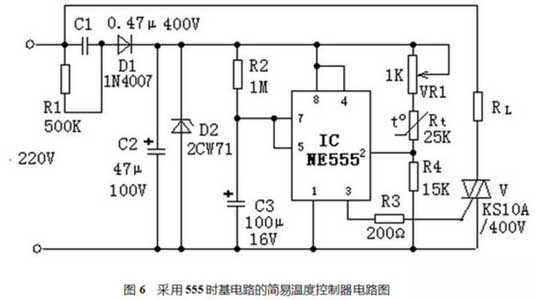
When the temperature is low, the negative temperature coefficient thermistor Rt has a large resistance. The 2 pin potential of the 555 time base integrated circuit (IC) is lower than 1/3 of the Ec voltage (about 4V), and the IC 3 pin outputs a high level. The triac V is triggered to conduct, and the electric heater RL is turned on for heating, thereby starting the timing cycle. When the temperature of the thermistor Rt placed at the temperature measuring point is higher than the set value and the timing cycle has not been completed, the heater RL is cut off after the end of the timing period. When the thermistor Rt temperature drops below the set value, the triac V is turned on again, and the electric heater RL is turned on for heating. This will achieve the purpose of automatic temperature control.
II. Component selection
In the circuit, the thermistor Rt can be of the MF12 type or the MF53 type with a negative temperature coefficient. It is also possible to select different resistance values and other types of negative temperature coefficient thermistors, as long as the relationship of Rt+VR1=2R4 is satisfied under the temperature conditions required for control. The larger the potentiometer VR1 can achieve a larger adjustment range, but the sensitivity will decrease. The triac V can also be selected according to the magnitude of the load current. There are no special requirements for other components, and parameters are selected according to the circuit diagram.
III. Production and debugging methods
The whole circuit can be installed on a circuit board, generally no debugging is required, and the time interval is 1.1R2 & TImes; C3 should be chosen to be smaller than the thermal time constant of the heating system, but it should not be too small, otherwise it will cause excessive radio frequency interference due to the rapid turn-on or turn-off of the triac V. After installation and commissioning, it can be loaded into a small plastic box and the thermistor Rt can be taken out to the temperature measurement point.
First, the circuit principle of the circuit
As shown in Figure 1.
When the temperature is low, the negative temperature coefficient thermistor Rt has a large resistance. The 2 pin potential of the 555 time base integrated circuit (IC) is lower than 1/3 of the Ec voltage (about 4V), and the IC 3 pin outputs a high level. The triac V is triggered to conduct, and the electric heater RL is turned on for heating, thereby starting the timing cycle. When the temperature of the thermistor Rt placed at the temperature measuring point is higher than the set value and the timing cycle has not been completed, the heater RL is cut off after the end of the timing period. When the thermistor Rt temperature drops below the set value, the triac V is turned on again, and the electric heater RL is turned on for heating. This will achieve the purpose of automatic temperature control.
II. Component selection
In the circuit, the thermistor Rt can be of the MF12 type or the MF53 type with a negative temperature coefficient. It is also possible to select different resistance values and other types of negative temperature coefficient thermistors, as long as the relationship of Rt+VR1=2R4 is satisfied under the temperature conditions required for control. The larger the potentiometer VR1 can achieve a larger adjustment range, but the sensitivity will decrease. The triac V can also be selected according to the magnitude of the load current. There are no special requirements for other components, and parameters are selected according to the circuit diagram.
III. Production and debugging methods
The whole circuit can be installed on a circuit board, generally no debugging is required, and the time interval is 1.1R2 & TImes; C3 should be chosen to be smaller than the thermal time constant of the heating system, but it should not be too small, otherwise it will cause excessive radio frequency interference due to the rapid turn-on or turn-off of the triac V. After installation and commissioning, it can be loaded into a small plastic box and the thermistor Rt can be taken out to the temperature measurement point.


